HP Cisco MDS 9020 Cisco MDS 9500 Series Hardware Installation Guide (OL-17467- - Page 117
System Grounding on, Appendix D, Technical Specifications, Step 1, Caution
 |
View all HP Cisco MDS 9020 manuals
Add to My Manuals
Save this manual to your list of manuals |
Page 117 highlights
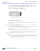
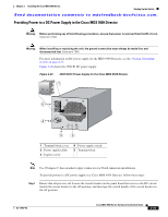
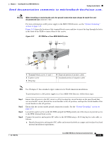
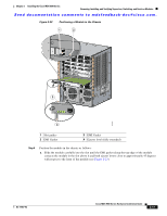
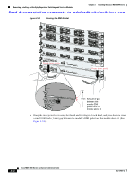
Chapter 2 Installing the Cisco MDS 9500 Series Starting Up the Switch Send documentation comments to [email protected]. To power up the switch and verify hardware operation, follow these steps: Step 1 Step 2 Step 3 Step 4 Step 5 Step 6 Step 7 Step 8 Verify that the faceplates of all modules are flush with the front of the chassis, and the ejector levers are fully closed and approximately parallel to the faceplate of the module. Verify that any empty module slots have filler panels installed. Verify that both power supplies and the fan module are installed. If any optional CompactFlash cards are installed, verify that the ejector button is popped out. Check the captive screws of the power supplies, fan module, and all supervisor, switching, or services modules, and tighten any loose captive screws. Ensure that the switch is adequately grounded as described in the "System Grounding" section on page 2-17, and that the power cables are connected to outlets that have the required AC or DC power voltages. See Appendix D, "Technical Specifications," for the required voltages. Power on the switch by turning the power switches on the power supplies or PEMs to the on (|) position or restoring power to the DC circuit, as required. The switch boots automatically. Listen for the fans; they should begin operating as soon as the switch is powered on. Caution Do not operate the switch without a functioning fan module except during the brief fan module replacement procedure. The Cisco MDS 9000 Family switches can operate for only a few minutes without a functioning fan module before they begin to overheat. Step 9 After the switch has finished booting, verify that the LED behavior is as follows: • Fan module: Status LED is green. • Power supplies: - Input OK LED is green. - Fan OK LED is green. - Output Fail LED is off. • Supervisor, switching, or services modules: - The System LED on the supervisor module is green, indicating that all chassis environmental monitors are reporting that the system is operational. If this LED is orange or red, then one or more environmental monitor is reporting a problem. - The Status LED on the switching or services modules flashes orange once, remains orange during diagnostic boot tests, then turns green when the module is operational (online). If the system software cannot start up, this LED remains orange or turns red. Note The LEDs for the Fibre Channel ports remain orange until the ports are enabled, and the LED for the MGMT 10/100 Ethernet port remains off until the port is connected. Step 10 If any LEDs other than the Fibre Channel port LEDs remain orange or red after the initial boot processes are complete, see Appendix D, "Technical Specifications." If a component is not operating correctly, try removing and reinstalling it. If it still does not operate correctly, contact your customer service representative for a replacement. OL-17467-02 Cisco MDS 9500 Series Hardware Installation Guide 2-37
-
 1
1 -
2
-
3
-
4
-
5
-
6
-
7
-
8
-
9
-
10
-
11
-
12
-
13
-
14
-
15
-
16
-
17
-
18
-
19
-
20
-
21
-
22
-
23
-
24
-
25
-
26
-
27
-
28
-
29
-
30
-
31
-
32
-
33
-
34
-
35
-
36
-
37
-
38
-
39
-
40
-
41
-
42
-
43
-
44
-
45
-
46
-
47
-
48
-
49
-
50
-
51
-
52
-
53
-
54
-
55
-
56
-
57
-
58
-
59
-
60
-
61
-
62
-
63
-
64
-
65
-
66
-
67
-
68
-
69
-
70
-
71
-
72
-
73
-
74
-
75
-
76
-
77
-
78
-
79
-
80
-
81
-
82
-
83
-
84
-
85
-
86
-
87
-
88
-
89
-
90
-
91
-
92
-
93
-
94
-
95
-
96
-
97
-
98
-
99
-
100
-
101
-
102
-
103
-
104
-
105
-
106
-
107
-
108
-
109
-
110
-
111
-
 112
112 -
 113
113 -
 114
114 -
 115
115 -
 116
116 -
 117
117 -
 118
118 -
 119
119 -
 120
120 -
 121
121 -
 122
122 -
123
-
124
-
125
-
126
-
127
-
128
-
129
-
130
-
131
-
132
-
133
-
134
-
135
-
136
-
137
-
138
-
139
-
140
-
141
-
142
-
143
-
144
-
145
-
146
-
147
-
148
-
149
-
150
-
151
-
152
-
153
-
154
-
155
-
156
-
157
-
158
-
159
-
160
-
161
-
162
-
163
-
164
-
165
-
166
-
167
-
168
-
169
-
170
-
171
-
172
-
173
-
174
-
175
-
176
-
177
-
178
-
179
-
180
-
181
-
182
-
183
-
184
-
185
-
186
-
187
-
188
-
189
-
190
-
191
-
192
-
193
-
194
-
195
-
196
-
197
-
198
-
199
-
200
-
201
-
202
-
203
-
204
-
205
-
206
-
207
-
208
-
209
-
210
-
211
-
212
-
213
-
214
-
215
-
216
-
217
-
218
-
219
-
220
-
221
-
222
-
223
-
224
-
225
-
226
-
227
-
228
-
229
-
230
-
231
-
232
-
233
-
234
-
235
-
236
-
237
-
238
-
239
-
240
-
241
-
242
-
243
-
244
-
245
-
246
-
247
-
248
-
249
-
250
-
251
-
252
-
253
-
254
-
255
-
256
-
257
-
258
-
259
-
260
-
261
-
262
-
263
-
264
-
265
-
266
-
267
-
268
-
269
-
270
-
271
-
272
-
273
-
274
-
275
-
276
-
277
-
278
-
279
-
280
-
281
-
282
-
283
-
284
-
285
-
286
-
287
-
288
 |
 |
