HP Cisco MDS 9020 Cisco MDS 9500 Series Hardware Installation Guide (OL-17467- - Page 146
Installing an AC PEM, Providing Power to an AC Power Supply for the Cisco
 |
View all HP Cisco MDS 9020 manuals
Add to My Manuals
Save this manual to your list of manuals |
Page 146 highlights
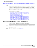
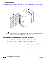
Removing and Installing a Power Supply or PEM Chapter 2 Installing the Cisco MDS 9500 Series Send documentation comments to [email protected]. Installing an AC PEM To install an AC PEM in a Cisco MDS 9506 chassis, follow these steps: Step 1 Step 2 Step 3 Step 4 Step 5 Ensure that the system (earth) ground connection has been made. See the "System Grounding" section on page 2-17. If a filler panel is installed, remove it from the PEM bay by loosening the captive screws and pulling it from the chassis. Slide the PEM into the PEM bay, ensuring that the PEM is fully seated in the bay. Tighten the PEM captive screws to 8 in-lb. Provide power to the PEM as described in the "Providing Power to an AC Power Supply for the Cisco MDS 9509 and Cisco MDS 9506 Directors" section on page 2-30. Caution In a system with dual power supplies, connect each power supply to a separate power source. In case of a power source failure, the second source will most likely still be available. Step 6 Verify PEM and power supply operation by checking the power supply LED states in the back of the chassis: • INPUT OK LED is green. • FAN OK LED is green. • OUTPUT FAIL LED is off. Installing a DC PEM To install a DC PEM in a Cisco MDS 9506 chassis, follow these steps: Step 1 Step 2 Step 3 Step 4 Step 5 Ensure that the system (earth) ground connection has been made. See the "System Grounding" section on page 2-17. If a filler panel is installed, remove it from the PEM bay by loosening the captive screws and pulling it from the chassis. Attach the DC power cables to the PEM as described in "Providing Power to a DC Power Supply in the Cisco MDS 9506 Director" section on page 2-34. Slide the PEM into the PEM bay, ensuring that the PEM is fully seated in the bay. Tighten the PEM captive screws to 8 in-lb. Caution In a system with dual power supplies, connect each power supply to a separate power source. In case of a power source failure, the second source will most likely still be available. Step 6 Verify PEM and power supply operation by checking the power supply LED states in the back of the chassis: • INPUT OK LED is green. • FAN OK LED is green. 2-66 Cisco MDS 9500 Series Hardware Installation Guide OL-17467-02
-
 1
1 -
2
-
3
-
4
-
5
-
6
-
7
-
8
-
9
-
10
-
11
-
12
-
13
-
14
-
15
-
16
-
17
-
18
-
19
-
20
-
21
-
22
-
23
-
24
-
25
-
26
-
27
-
28
-
29
-
30
-
31
-
32
-
33
-
34
-
35
-
36
-
37
-
38
-
39
-
40
-
41
-
42
-
43
-
44
-
45
-
46
-
47
-
48
-
49
-
50
-
51
-
52
-
53
-
54
-
55
-
56
-
57
-
58
-
59
-
60
-
61
-
62
-
63
-
64
-
65
-
66
-
67
-
68
-
69
-
70
-
71
-
72
-
73
-
74
-
75
-
76
-
77
-
78
-
79
-
80
-
81
-
82
-
83
-
84
-
85
-
86
-
87
-
88
-
89
-
90
-
91
-
92
-
93
-
94
-
95
-
96
-
97
-
98
-
99
-
100
-
101
-
102
-
103
-
104
-
105
-
106
-
107
-
108
-
109
-
110
-
111
-
112
-
113
-
114
-
115
-
116
-
117
-
118
-
119
-
120
-
121
-
122
-
123
-
124
-
125
-
126
-
127
-
128
-
129
-
130
-
131
-
132
-
133
-
134
-
135
-
136
-
137
-
138
-
139
-
140
-
 141
141 -
 142
142 -
 143
143 -
 144
144 -
 145
145 -
 146
146 -
 147
147 -
 148
148 -
 149
149 -
 150
150 -
 151
151 -
152
-
153
-
154
-
155
-
156
-
157
-
158
-
159
-
160
-
161
-
162
-
163
-
164
-
165
-
166
-
167
-
168
-
169
-
170
-
171
-
172
-
173
-
174
-
175
-
176
-
177
-
178
-
179
-
180
-
181
-
182
-
183
-
184
-
185
-
186
-
187
-
188
-
189
-
190
-
191
-
192
-
193
-
194
-
195
-
196
-
197
-
198
-
199
-
200
-
201
-
202
-
203
-
204
-
205
-
206
-
207
-
208
-
209
-
210
-
211
-
212
-
213
-
214
-
215
-
216
-
217
-
218
-
219
-
220
-
221
-
222
-
223
-
224
-
225
-
226
-
227
-
228
-
229
-
230
-
231
-
232
-
233
-
234
-
235
-
236
-
237
-
238
-
239
-
240
-
241
-
242
-
243
-
244
-
245
-
246
-
247
-
248
-
249
-
250
-
251
-
252
-
253
-
254
-
255
-
256
-
257
-
258
-
259
-
260
-
261
-
262
-
263
-
264
-
265
-
266
-
267
-
268
-
269
-
270
-
271
-
272
-
273
-
274
-
275
-
276
-
277
-
278
-
279
-
280
-
281
-
282
-
283
-
284
-
285
-
286
-
287
-
288
 |
 |
