HP Cisco MDS 9020 Cisco MDS 9500 Series Hardware Installation Guide (OL-17467- - Page 158
Clock Module Replacement on the Cisco MDS 9513 Director Rear View, Step 3
 |
View all HP Cisco MDS 9020 manuals
Add to My Manuals
Save this manual to your list of manuals |
Page 158 highlights
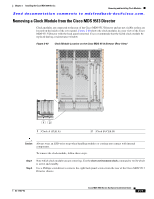
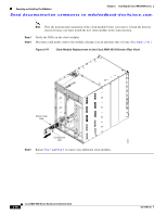
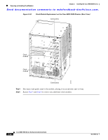
Removing and Installing Clock Modules Chapter 2 Installing the Cisco MDS 9500 Series Send documentation comments to [email protected]. Note Note the position and orientation of the clock module before you remove it from the director chassis because you must install the new clock module in the same position. Step 3 Verify the LEDs on the clock modules. Step 4 Disconnect and gently remove the module, placing it on an antistatic mat or foam. (See Figure 2-41.) Figure 2-41 Clock Module Replacement on the Cisco MDS 9513 Director (Rear View) Sheet metal side Component side Step 5 Repeat Step 3 and Step 4 to remove any additional clock modules. 144602 2-78 Cisco MDS 9500 Series Hardware Installation Guide OL-17467-02
-
 1
1 -
2
-
3
-
4
-
5
-
6
-
7
-
8
-
9
-
10
-
11
-
12
-
13
-
14
-
15
-
16
-
17
-
18
-
19
-
20
-
21
-
22
-
23
-
24
-
25
-
26
-
27
-
28
-
29
-
30
-
31
-
32
-
33
-
34
-
35
-
36
-
37
-
38
-
39
-
40
-
41
-
42
-
43
-
44
-
45
-
46
-
47
-
48
-
49
-
50
-
51
-
52
-
53
-
54
-
55
-
56
-
57
-
58
-
59
-
60
-
61
-
62
-
63
-
64
-
65
-
66
-
67
-
68
-
69
-
70
-
71
-
72
-
73
-
74
-
75
-
76
-
77
-
78
-
79
-
80
-
81
-
82
-
83
-
84
-
85
-
86
-
87
-
88
-
89
-
90
-
91
-
92
-
93
-
94
-
95
-
96
-
97
-
98
-
99
-
100
-
101
-
102
-
103
-
104
-
105
-
106
-
107
-
108
-
109
-
110
-
111
-
112
-
113
-
114
-
115
-
116
-
117
-
118
-
119
-
120
-
121
-
122
-
123
-
124
-
125
-
126
-
127
-
128
-
129
-
130
-
131
-
132
-
133
-
134
-
135
-
136
-
137
-
138
-
139
-
140
-
141
-
142
-
143
-
144
-
145
-
146
-
147
-
148
-
149
-
150
-
151
-
152
-
 153
153 -
 154
154 -
 155
155 -
 156
156 -
 157
157 -
 158
158 -
 159
159 -
 160
160 -
 161
161 -
 162
162 -
 163
163 -
164
-
165
-
166
-
167
-
168
-
169
-
170
-
171
-
172
-
173
-
174
-
175
-
176
-
177
-
178
-
179
-
180
-
181
-
182
-
183
-
184
-
185
-
186
-
187
-
188
-
189
-
190
-
191
-
192
-
193
-
194
-
195
-
196
-
197
-
198
-
199
-
200
-
201
-
202
-
203
-
204
-
205
-
206
-
207
-
208
-
209
-
210
-
211
-
212
-
213
-
214
-
215
-
216
-
217
-
218
-
219
-
220
-
221
-
222
-
223
-
224
-
225
-
226
-
227
-
228
-
229
-
230
-
231
-
232
-
233
-
234
-
235
-
236
-
237
-
238
-
239
-
240
-
241
-
242
-
243
-
244
-
245
-
246
-
247
-
248
-
249
-
250
-
251
-
252
-
253
-
254
-
255
-
256
-
257
-
258
-
259
-
260
-
261
-
262
-
263
-
264
-
265
-
266
-
267
-
268
-
269
-
270
-
271
-
272
-
273
-
274
-
275
-
276
-
277
-
278
-
279
-
280
-
281
-
282
-
283
-
284
-
285
-
286
-
287
-
288
 |
 |

Send documentation comments to [email protected].
2-78
Cisco MDS 9500 Series Hardware Installation Guide
OL-17467-02
Chapter 2
Installing the Cisco MDS 9500 Series
Removing and Installing Clock Modules
Note
Note the position and orientation of the clock module before you remove it from the director
chassis because you must install the new clock module in the same position.
Step 3
Verify the LEDs on the clock modules.
Step 4
Disconnect and gently remove the module, placing it on an antistatic mat or foam. (See
Figure 2-41
.)
Figure 2-41
Clock Module Replacement on the Cisco MDS 9513 Director (Rear View)
Step 5
Repeat
Step 3
and
Step 4
to remove any additional clock modules.
144602
Component
side
Sheet metal
side