HP Cisco MDS 9020 Cisco MDS 9500 Series Hardware Installation Guide (OL-17467- - Page 115
When installing or replacing the unit, the ground connection must always be made first
 |
View all HP Cisco MDS 9020 manuals
Add to My Manuals
Save this manual to your list of manuals |
Page 115 highlights
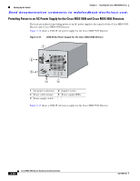
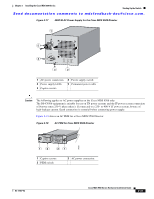
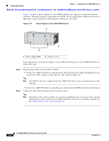
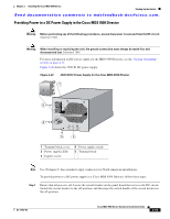
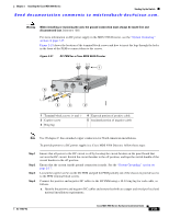
Chapter 2 Installing the Cisco MDS 9500 Series Starting Up the Switch Send documentation comments to [email protected]. Warning When installing or replacing the unit, the ground connection must always be made first and disconnected last. Statement 1046 For more information on DC power supply in the MDS 9506 Director, see the "System Grounding" section on page 2-17. Figure 2-21 shows the location of the terminal block screws and how to insert the lugs through the holes in the front of the PEM to connect them to the screws. Figure 2-21 DC PEM for a Cisco MDS 9506 Director () () 1 5 99293 () () 4 3 2 1 Terminal block screws (+ and -) 2 Captive screw 3 Ring lug 4 Exposed portion of positive cable 5 Insulated portion of negative cable Note Use 90-degree C fine-stranded copper conductors for North American installations. To provide power to a DC power supply in a Cisco MDS 9506 Director, follow these steps: Step 1 Step 2 Step 3 Step 4 Ensure that all power to the DC circuit is off by locating the circuit breaker on the panel board that services the DC circuit. Switch the circuit breaker to the off position, and tape the switch handle of the circuit breaker in the off position. Ensure that the system (earth) ground connection is made. See the "System Grounding" section on page 2-17. Loosen the captive screws on the DC PEM and pull the PEM partially out of the chassis to provide access to the PEM terminal block screws. Connect the positive and negative DC cables to the DC PEM using a 10-32 ring lug for each cable, as follows: a. Identify the positive and negative DC cables and ensure that both are copper and sized per local and national installation requirements. OL-17467-02 Cisco MDS 9500 Series Hardware Installation Guide 2-35
-
 1
1 -
2
-
3
-
4
-
5
-
6
-
7
-
8
-
9
-
10
-
11
-
12
-
13
-
14
-
15
-
16
-
17
-
18
-
19
-
20
-
21
-
22
-
23
-
24
-
25
-
26
-
27
-
28
-
29
-
30
-
31
-
32
-
33
-
34
-
35
-
36
-
37
-
38
-
39
-
40
-
41
-
42
-
43
-
44
-
45
-
46
-
47
-
48
-
49
-
50
-
51
-
52
-
53
-
54
-
55
-
56
-
57
-
58
-
59
-
60
-
61
-
62
-
63
-
64
-
65
-
66
-
67
-
68
-
69
-
70
-
71
-
72
-
73
-
74
-
75
-
76
-
77
-
78
-
79
-
80
-
81
-
82
-
83
-
84
-
85
-
86
-
87
-
88
-
89
-
90
-
91
-
92
-
93
-
94
-
95
-
96
-
97
-
98
-
99
-
100
-
101
-
102
-
103
-
104
-
105
-
106
-
107
-
108
-
109
-
 110
110 -
 111
111 -
 112
112 -
 113
113 -
 114
114 -
 115
115 -
 116
116 -
 117
117 -
 118
118 -
 119
119 -
 120
120 -
121
-
122
-
123
-
124
-
125
-
126
-
127
-
128
-
129
-
130
-
131
-
132
-
133
-
134
-
135
-
136
-
137
-
138
-
139
-
140
-
141
-
142
-
143
-
144
-
145
-
146
-
147
-
148
-
149
-
150
-
151
-
152
-
153
-
154
-
155
-
156
-
157
-
158
-
159
-
160
-
161
-
162
-
163
-
164
-
165
-
166
-
167
-
168
-
169
-
170
-
171
-
172
-
173
-
174
-
175
-
176
-
177
-
178
-
179
-
180
-
181
-
182
-
183
-
184
-
185
-
186
-
187
-
188
-
189
-
190
-
191
-
192
-
193
-
194
-
195
-
196
-
197
-
198
-
199
-
200
-
201
-
202
-
203
-
204
-
205
-
206
-
207
-
208
-
209
-
210
-
211
-
212
-
213
-
214
-
215
-
216
-
217
-
218
-
219
-
220
-
221
-
222
-
223
-
224
-
225
-
226
-
227
-
228
-
229
-
230
-
231
-
232
-
233
-
234
-
235
-
236
-
237
-
238
-
239
-
240
-
241
-
242
-
243
-
244
-
245
-
246
-
247
-
248
-
249
-
250
-
251
-
252
-
253
-
254
-
255
-
256
-
257
-
258
-
259
-
260
-
261
-
262
-
263
-
264
-
265
-
266
-
267
-
268
-
269
-
270
-
271
-
272
-
273
-
274
-
275
-
276
-
277
-
278
-
279
-
280
-
281
-
282
-
283
-
284
-
285
-
286
-
287
-
288
 |
 |
