HP Cisco MDS 9020 Cisco MDS 9500 Series Hardware Installation Guide (OL-17467- - Page 121
EMI Gasket, Positioning a Module in the Chassis
 |
View all HP Cisco MDS 9020 manuals
Add to My Manuals
Save this manual to your list of manuals |
Page 121 highlights
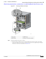
Chapter 2 Installing the Cisco MDS 9500 Series Removing, Installing, and Verifying Supervisor, Switching, and Services Modules Send documentation comments to [email protected]. Figure 2-22 Positioning a Module in the Chassis 1 2 3 4 4 5 66 3 94987 4 1 Slot guides 2 EMI Gasket 3 EMI Gasket 4 Ejector level (fully extended) Step 6 Position the module in the chassis as follows: a. Slide the module carefully into the slot until the EMI gasket along the top edge of the module contacts the module in the slot above it and both ejector levers close to approximately 45 degrees with respect to the front of the module (see Figure 2-23). OL-17467-02 Cisco MDS 9500 Series Hardware Installation Guide 2-41
-
 1
1 -
2
-
3
-
4
-
5
-
6
-
7
-
8
-
9
-
10
-
11
-
12
-
13
-
14
-
15
-
16
-
17
-
18
-
19
-
20
-
21
-
22
-
23
-
24
-
25
-
26
-
27
-
28
-
29
-
30
-
31
-
32
-
33
-
34
-
35
-
36
-
37
-
38
-
39
-
40
-
41
-
42
-
43
-
44
-
45
-
46
-
47
-
48
-
49
-
50
-
51
-
52
-
53
-
54
-
55
-
56
-
57
-
58
-
59
-
60
-
61
-
62
-
63
-
64
-
65
-
66
-
67
-
68
-
69
-
70
-
71
-
72
-
73
-
74
-
75
-
76
-
77
-
78
-
79
-
80
-
81
-
82
-
83
-
84
-
85
-
86
-
87
-
88
-
89
-
90
-
91
-
92
-
93
-
94
-
95
-
96
-
97
-
98
-
99
-
100
-
101
-
102
-
103
-
104
-
105
-
106
-
107
-
108
-
109
-
110
-
111
-
112
-
113
-
114
-
115
-
 116
116 -
 117
117 -
 118
118 -
 119
119 -
 120
120 -
 121
121 -
 122
122 -
 123
123 -
 124
124 -
 125
125 -
 126
126 -
127
-
128
-
129
-
130
-
131
-
132
-
133
-
134
-
135
-
136
-
137
-
138
-
139
-
140
-
141
-
142
-
143
-
144
-
145
-
146
-
147
-
148
-
149
-
150
-
151
-
152
-
153
-
154
-
155
-
156
-
157
-
158
-
159
-
160
-
161
-
162
-
163
-
164
-
165
-
166
-
167
-
168
-
169
-
170
-
171
-
172
-
173
-
174
-
175
-
176
-
177
-
178
-
179
-
180
-
181
-
182
-
183
-
184
-
185
-
186
-
187
-
188
-
189
-
190
-
191
-
192
-
193
-
194
-
195
-
196
-
197
-
198
-
199
-
200
-
201
-
202
-
203
-
204
-
205
-
206
-
207
-
208
-
209
-
210
-
211
-
212
-
213
-
214
-
215
-
216
-
217
-
218
-
219
-
220
-
221
-
222
-
223
-
224
-
225
-
226
-
227
-
228
-
229
-
230
-
231
-
232
-
233
-
234
-
235
-
236
-
237
-
238
-
239
-
240
-
241
-
242
-
243
-
244
-
245
-
246
-
247
-
248
-
249
-
250
-
251
-
252
-
253
-
254
-
255
-
256
-
257
-
258
-
259
-
260
-
261
-
262
-
263
-
264
-
265
-
266
-
267
-
268
-
269
-
270
-
271
-
272
-
273
-
274
-
275
-
276
-
277
-
278
-
279
-
280
-
281
-
282
-
283
-
284
-
285
-
286
-
287
-
288
 |
 |

Send documentation comments to [email protected].
2-41
Cisco MDS 9500 Series Hardware Installation Guide
OL-17467-02
Chapter 2
Installing the Cisco MDS 9500 Series
Removing, Installing, and Verifying Supervisor, Switching, and Services Modules
Figure 2-22
Positioning a Module in the Chassis
Step 6
Position the module in the chassis as follows:
a.
Slide the module carefully into the slot until the EMI gasket along the top edge of the module
contacts the module in the slot above it and both ejector levers close to approximately 45 degrees
with respect to the front of the module (see
Figure 2-23
).
1
Slot guides
3
EMI Gasket
2
EMI Gasket
4
Ejector level (fully extended)
94987
4
3
5
4
6
6
1
2
3
4