HP Cisco MDS 9020 Cisco MDS 9500 Series Hardware Installation Guide (OL-17467- - Page 189
Connecting to a Fibre Channel Port, Removing and Installing X2 Transceivers
 |
View all HP Cisco MDS 9020 manuals
Add to My Manuals
Save this manual to your list of manuals |
Page 189 highlights
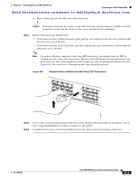
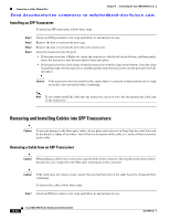
Chapter B Connecting the Cisco MDS 9500 Series Connecting to a Fibre Channel Port Send documentation comments to [email protected]. Connecting to a Fibre Channel Port The Fibre Channel ports on the switching modules are compatible with LC-type fiber-optic SFP transceivers and cables. You can use these ports to connect to the SAN or for in-band management. For information about configuring the switch for in-band management, see the Cisco MDS 9000 Family CLI Configuration Guide. The Cisco MDS 9000 Family supports both Fibre Channel and Gigabit Ethernet protocols for SFP transceivers. Each transceiver must match the transceiver on the other end of the cable, and the cable must not exceed the stipulated cable length for reliable communication. For information on how to get the list of supported SFP transceivers for your software release, see the Cisco MDS 9000 Family Release Notes for Cisco MDS SAN-OS. Warning Class 1 laser product. Statement 1008 Warning Invisible laser radiation may be emitted from disconnected fibers or connectors. Do not stare into beams or view directly with optical instruments. Statement 1051 Caution Wear an ESD wrist strap connected to the chassis when handling transceivers. Keep optical connectors covered when not in use, and do not touch connector ends. The fiber-optic connectors must be free of dust, oil, and other contaminants. This section provides the following topics: • Removing and Installing X2 Transceivers, page B-9 • Removing and Installing SFP Transceivers, page B-12 • Removing and Installing Cables into SFP Transceivers, page B-14 • Maintaining SFP Transceivers and Fiber-Optic Cables, page B-16 Removing and Installing X2 Transceivers Caution Excessively removing and installing X2 transceivers can shorten its useful life. Do not remove and insert X2 transceivers more often than is absolutely necessary. We recommend disconnecting cables before installing or removing SFP transceivers to prevent damage to the cable or transceiver. Note Use only Cisco X2 transceivers listed in Table D-19 on page D-20 on the Cisco MDS 9200 Series. Each X2 transceiver is encoded with model information that enables the switch to verify that the X2 transceiver meets the requirements for the switch. For instructions specific to the transceiver type, see the "X2 Transceiver Specifications" section on page D-19. OL-17467-02 Cisco MDS 9500 Series Hardware Installation Guide B-9
-
 1
1 -
2
-
3
-
4
-
5
-
6
-
7
-
8
-
9
-
10
-
11
-
12
-
13
-
14
-
15
-
16
-
17
-
18
-
19
-
20
-
21
-
22
-
23
-
24
-
25
-
26
-
27
-
28
-
29
-
30
-
31
-
32
-
33
-
34
-
35
-
36
-
37
-
38
-
39
-
40
-
41
-
42
-
43
-
44
-
45
-
46
-
47
-
48
-
49
-
50
-
51
-
52
-
53
-
54
-
55
-
56
-
57
-
58
-
59
-
60
-
61
-
62
-
63
-
64
-
65
-
66
-
67
-
68
-
69
-
70
-
71
-
72
-
73
-
74
-
75
-
76
-
77
-
78
-
79
-
80
-
81
-
82
-
83
-
84
-
85
-
86
-
87
-
88
-
89
-
90
-
91
-
92
-
93
-
94
-
95
-
96
-
97
-
98
-
99
-
100
-
101
-
102
-
103
-
104
-
105
-
106
-
107
-
108
-
109
-
110
-
111
-
112
-
113
-
114
-
115
-
116
-
117
-
118
-
119
-
120
-
121
-
122
-
123
-
124
-
125
-
126
-
127
-
128
-
129
-
130
-
131
-
132
-
133
-
134
-
135
-
136
-
137
-
138
-
139
-
140
-
141
-
142
-
143
-
144
-
145
-
146
-
147
-
148
-
149
-
150
-
151
-
152
-
153
-
154
-
155
-
156
-
157
-
158
-
159
-
160
-
161
-
162
-
163
-
164
-
165
-
166
-
167
-
168
-
169
-
170
-
171
-
172
-
173
-
174
-
175
-
176
-
177
-
178
-
179
-
180
-
181
-
182
-
183
-
 184
184 -
 185
185 -
 186
186 -
 187
187 -
 188
188 -
 189
189 -
 190
190 -
 191
191 -
 192
192 -
 193
193 -
 194
194 -
195
-
196
-
197
-
198
-
199
-
200
-
201
-
202
-
203
-
204
-
205
-
206
-
207
-
208
-
209
-
210
-
211
-
212
-
213
-
214
-
215
-
216
-
217
-
218
-
219
-
220
-
221
-
222
-
223
-
224
-
225
-
226
-
227
-
228
-
229
-
230
-
231
-
232
-
233
-
234
-
235
-
236
-
237
-
238
-
239
-
240
-
241
-
242
-
243
-
244
-
245
-
246
-
247
-
248
-
249
-
250
-
251
-
252
-
253
-
254
-
255
-
256
-
257
-
258
-
259
-
260
-
261
-
262
-
263
-
264
-
265
-
266
-
267
-
268
-
269
-
270
-
271
-
272
-
273
-
274
-
275
-
276
-
277
-
278
-
279
-
280
-
281
-
282
-
283
-
284
-
285
-
286
-
287
-
288
 |
 |
