HP Cisco MDS 9020 Cisco MDS 9500 Series Hardware Installation Guide (OL-17467- - Page 126
Verifying Installation of Supervisor, Switching, and Services Modules
 |
View all HP Cisco MDS 9020 manuals
Add to My Manuals
Save this manual to your list of manuals |
Page 126 highlights
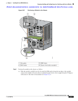
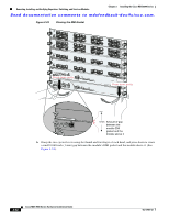
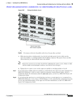
Removing, Installing, and Verifying Supervisor, Switching, and Services Modules Chapter 2 Installing the Cisco MDS 9500 Series Send documentation comments to [email protected]. Step 5 Step 6 Step 7 If a filler panel is installed, remove the two Phillips pan-head screws from the filler panel and remove the panel. To remove a currently installed module, see the "Removing Other Switching and Services Modules" section on page 2-45. Open both the ejector levers on the new or replacement module completely. (See Figure 2-22.) Position the module in the chassis as follows: a. Position the module in the slot. Ensure that you align the sides of the module carrier with the slot guides on each side of the slot. b. Slide the module carefully into the slot until the EMI gasket along the top edge of the module contacts the module in the slot above it and both ejector levers close to approximately 45 degrees with respect to the front of the module. (See Figure 2-23.) c. Grasp the two ejector levers using the thumb and forefinger of each hand, and press down to create a small 0.040-inch (1-mm) gap between the module's EMI gasket and the module above it. (See Figure 2-24.) Caution Do not press down too forcefully on the levers because they can bend. d. While pressing down, simultaneously close the left and right ejector levers to fully seat the supervisor module or switching module in the backplane connector. The ejector levers are fully closed when they are flush with the front of the module. Note Ensure the ejector levers are fully closed before tightening the captive screws. Failure to fully seat the module in the backplane connector can result in error messages. Step 8 Step 9 e. Tighten the two captive screws on the supervisor module or switching module to 8 in-lb. If you replaced the standby supervisor module in a switch that has two supervisors and is running Cisco MDS SAN-OS Release 1.2(2a) or earlier, enable the automatic synchronization feature, which is disabled by default. For information about the auto-sync option, see the Cisco MDS 9000 Family CLI Configuration Guide. If you replaced the supervisor in a switch that does not have a second supervisor or is running Cisco MDS SAN-OS Release 1.3(1) or later or NX-OS Release 4.1(1b), download the configuration from the server to the nonvolatile memory of the supervisor. For more information, see the Cisco MDS 9000 Family CLI Configuration Guide. Verifying Installation of Supervisor, Switching, and Services Modules To verify the module installation, follow these steps: Step 1 Step 2 Step 3 Verify that the ejector levers of each module are fully closed (parallel to the front of the module) to ensure that the supervisor module and all switching or services modules are fully seated in the backplane connectors. Check the captive screws of each module, the power supply, and the fan module. Tighten any loose captive screws to 8 in-lb. Verify that any empty module slots have filler panels installed and that the screws holding the panels in place are tight. 2-46 Cisco MDS 9500 Series Hardware Installation Guide OL-17467-02
-
 1
1 -
2
-
3
-
4
-
5
-
6
-
7
-
8
-
9
-
10
-
11
-
12
-
13
-
14
-
15
-
16
-
17
-
18
-
19
-
20
-
21
-
22
-
23
-
24
-
25
-
26
-
27
-
28
-
29
-
30
-
31
-
32
-
33
-
34
-
35
-
36
-
37
-
38
-
39
-
40
-
41
-
42
-
43
-
44
-
45
-
46
-
47
-
48
-
49
-
50
-
51
-
52
-
53
-
54
-
55
-
56
-
57
-
58
-
59
-
60
-
61
-
62
-
63
-
64
-
65
-
66
-
67
-
68
-
69
-
70
-
71
-
72
-
73
-
74
-
75
-
76
-
77
-
78
-
79
-
80
-
81
-
82
-
83
-
84
-
85
-
86
-
87
-
88
-
89
-
90
-
91
-
92
-
93
-
94
-
95
-
96
-
97
-
98
-
99
-
100
-
101
-
102
-
103
-
104
-
105
-
106
-
107
-
108
-
109
-
110
-
111
-
112
-
113
-
114
-
115
-
116
-
117
-
118
-
119
-
120
-
 121
121 -
 122
122 -
 123
123 -
 124
124 -
 125
125 -
 126
126 -
 127
127 -
 128
128 -
 129
129 -
 130
130 -
 131
131 -
132
-
133
-
134
-
135
-
136
-
137
-
138
-
139
-
140
-
141
-
142
-
143
-
144
-
145
-
146
-
147
-
148
-
149
-
150
-
151
-
152
-
153
-
154
-
155
-
156
-
157
-
158
-
159
-
160
-
161
-
162
-
163
-
164
-
165
-
166
-
167
-
168
-
169
-
170
-
171
-
172
-
173
-
174
-
175
-
176
-
177
-
178
-
179
-
180
-
181
-
182
-
183
-
184
-
185
-
186
-
187
-
188
-
189
-
190
-
191
-
192
-
193
-
194
-
195
-
196
-
197
-
198
-
199
-
200
-
201
-
202
-
203
-
204
-
205
-
206
-
207
-
208
-
209
-
210
-
211
-
212
-
213
-
214
-
215
-
216
-
217
-
218
-
219
-
220
-
221
-
222
-
223
-
224
-
225
-
226
-
227
-
228
-
229
-
230
-
231
-
232
-
233
-
234
-
235
-
236
-
237
-
238
-
239
-
240
-
241
-
242
-
243
-
244
-
245
-
246
-
247
-
248
-
249
-
250
-
251
-
252
-
253
-
254
-
255
-
256
-
257
-
258
-
259
-
260
-
261
-
262
-
263
-
264
-
265
-
266
-
267
-
268
-
269
-
270
-
271
-
272
-
273
-
274
-
275
-
276
-
277
-
278
-
279
-
280
-
281
-
282
-
283
-
284
-
285
-
286
-
287
-
288
 |
 |
