HP P3410A HP NetRAID 1M/2M Installation & Configuration - Page 52
Step E., Install Cables
 |
UPC - 725184582783
View all HP P3410A manuals
Add to My Manuals
Save this manual to your list of manuals |
Page 52 highlights
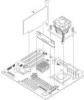
Chapter 5 Installation and Configuration 3. Install the adapter by following the installation instructions for installing PCI boards in your host system manual and on the chassis labels. Align the adapter card bus connector into the slot. Ensure that it does not physically interfere with adjacent cards. Press the card gently but firmly into the slot to seat it properly. The bottom edge of the card should be flush with the slot. Secure the adapter to the system chassis with a mounting screw. CAUTION The adapter is sensitive to static electricity and can easily be damaged by improper handling. The use of a grounding strap is recommended. Before you remove the adapter from the bag, touch a grounded, unpainted metal surface on the system to discharge static electricity. Step E. Install Cables In this step, you connect the adapter's SCSI channels to the physical drives listed in Worksheet A. Connect Cables Install the cables to create the hardware setup you planned in Worksheet A. Refer to the system documentation and the Hot Swap Disk Subsystem Cabling Information label on the chassis for factory default cable configurations. NOTE For additional information, refer to the HP Rack Storage/12 Installation Guide. Install and remove SCSI cables as follows: • SCSI cable connectors must be plugged in or removed evenly, not one end first, to avoid bending the pins. Use the white pull-tab, if present, when removing a connector. • For backplane connectors with locking ears, open the locking ears before inserting the SCSI cable. 44
-
 1
1 -
2
-
3
-
4
-
5
-
6
-
7
-
8
-
9
-
10
-
11
-
12
-
13
-
14
-
15
-
16
-
17
-
18
-
19
-
20
-
21
-
22
-
23
-
24
-
25
-
26
-
27
-
28
-
29
-
30
-
31
-
32
-
33
-
34
-
35
-
36
-
37
-
38
-
39
-
40
-
41
-
42
-
43
-
44
-
45
-
46
-
 47
47 -
 48
48 -
 49
49 -
 50
50 -
 51
51 -
 52
52 -
 53
53 -
 54
54 -
 55
55 -
 56
56 -
 57
57 -
58
-
59
-
60
-
61
-
62
-
63
-
64
-
65
-
66
-
67
-
68
-
69
-
70
-
71
-
72
-
73
-
74
-
75
-
76
-
77
-
78
-
79
-
80
-
81
-
82
-
83
-
84
-
85
-
86
-
87
-
88
-
89
-
90
-
91
-
92
-
93
-
94
-
95
-
96
-
97
-
98
-
99
-
100
-
101
-
102
-
103
-
104
-
105
-
106
-
107
-
108
-
109
-
110
-
111
-
112
-
113
-
114
-
115
-
116
-
117
-
118
-
119
-
120
-
121
-
122
-
123
-
124
-
125
-
126
-
127
-
128
-
129
-
130
-
131
-
132
-
133
-
134
-
135
-
136
-
137
-
138
-
139
-
140
-
141
-
142
-
143
-
144
-
145
-
146
-
147
-
148
-
149
-
150
-
151
-
152
-
153
-
154
-
155
-
156
-
157
-
158
-
159
-
160
-
161
-
162
-
163
-
164
-
165
-
166
-
167
-
168
-
169
-
170
-
171
-
172
-
173
-
174
-
175
-
176
-
177
-
178
-
179
-
180
-
181
-
182
-
183
 |
 |
