HP Pro 3080 Maintenance & Service Guide: HP Pro 3000/3010/3080 Business PC - Page 116
Installing the Guide Screw in the Optical Drive,
 |
View all HP Pro 3080 manuals
Add to My Manuals
Save this manual to your list of manuals |
Page 116 highlights
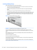
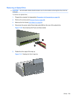
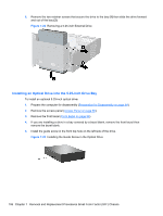
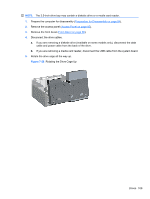
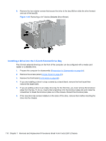
6. Remove the two retainer screws that secure the drive to the bay (1) then slide the drive forward and out of the bay (2). Figure 7-22 Removing a 5.25-inch External Drive Installing an Optical Drive into the 5.25-inch Drive Bay To install an optional 5.25-inch optical drive: 1. Prepare the computer for disassembly (Preparation for Disassembly on page 84). 2. Remove the access panel (Access Panel on page 85). 3. Remove the front bezel (Front Bezel on page 86). 4. If you are installing a drive in a bay covered by a bezel blank, remove the front bezel then remove the bezel blank. 5. Install the guide screw in the front top hole on the left side of the drive. Figure 7-23 Installing the Guide Screw in the Optical Drive 106 Chapter 7 Removal and Replacement Procedures Small Form Factor (SFF) Chassis
-
 1
1 -
2
-
3
-
4
-
5
-
6
-
7
-
8
-
9
-
10
-
11
-
12
-
13
-
14
-
15
-
16
-
17
-
18
-
19
-
20
-
21
-
22
-
23
-
24
-
25
-
26
-
27
-
28
-
29
-
30
-
31
-
32
-
33
-
34
-
35
-
36
-
37
-
38
-
39
-
40
-
41
-
42
-
43
-
44
-
45
-
46
-
47
-
48
-
49
-
50
-
51
-
52
-
53
-
54
-
55
-
56
-
57
-
58
-
59
-
60
-
61
-
62
-
63
-
64
-
65
-
66
-
67
-
68
-
69
-
70
-
71
-
72
-
73
-
74
-
75
-
76
-
77
-
78
-
79
-
80
-
81
-
82
-
83
-
84
-
85
-
86
-
87
-
88
-
89
-
90
-
91
-
92
-
93
-
94
-
95
-
96
-
97
-
98
-
99
-
100
-
101
-
102
-
103
-
104
-
105
-
106
-
107
-
108
-
109
-
110
-
 111
111 -
 112
112 -
 113
113 -
 114
114 -
 115
115 -
 116
116 -
 117
117 -
 118
118 -
 119
119 -
 120
120 -
 121
121 -
122
-
123
-
124
-
125
-
126
-
127
-
128
-
129
-
130
-
131
-
132
-
133
-
134
-
135
-
136
-
137
-
138
-
139
-
140
-
141
-
142
-
143
-
144
-
145
-
146
-
147
-
148
-
149
-
150
-
151
-
152
-
153
-
154
-
155
-
156
-
157
-
158
-
159
-
160
-
161
-
162
-
163
-
164
-
165
-
166
-
167
-
168
-
169
-
170
-
171
-
172
-
173
-
174
-
175
-
176
-
177
-
178
-
179
-
180
-
181
-
182
-
183
-
184
-
185
-
186
-
187
-
188
-
189
-
190
-
191
-
192
-
193
-
194
 |
 |
