HP Pro 3080 Maintenance & Service Guide: HP Pro 3000/3010/3080 Business PC - Page 118
Removing an External 3.5-inch Drive, Connecting the Power and Data Cables
 |
View all HP Pro 3080 manuals
Add to My Manuals
Save this manual to your list of manuals |
Page 118 highlights
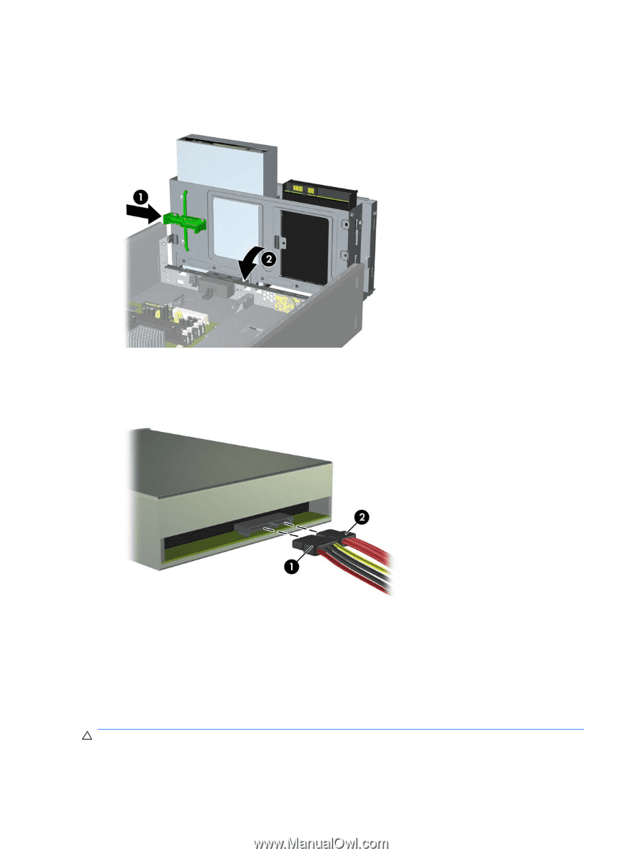
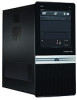
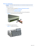
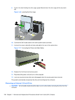
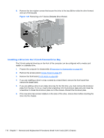
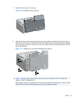
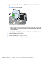
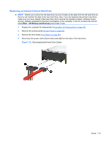
9. Push in the latch holding the drive cage upright (1) and lower the drive cage all the way down (2). Figure 7-26 Lowering the Drive Cage 10. Connect the SATA data cable to the white system board connector. 11. Connect the power cable (1) and data cable (2) to the rear of the optical drive. Figure 7-27 Connecting the Power and Data Cables 12. Replace the front bezel and access panel. 13. Reconnect the power cord and turn on the computer. 14. Lock any security devices that were disengaged when the access panel was removed. The system automatically recognizes the drive and reconfigures the computer. Removing an External 3.5-inch Drive CAUTION: All removable media should be taken out of a drive before removing the drive from the computer. 108 Chapter 7 Removal and Replacement Procedures Small Form Factor (SFF) Chassis
-
 1
1 -
2
-
3
-
4
-
5
-
6
-
7
-
8
-
9
-
10
-
11
-
12
-
13
-
14
-
15
-
16
-
17
-
18
-
19
-
20
-
21
-
22
-
23
-
24
-
25
-
26
-
27
-
28
-
29
-
30
-
31
-
32
-
33
-
34
-
35
-
36
-
37
-
38
-
39
-
40
-
41
-
42
-
43
-
44
-
45
-
46
-
47
-
48
-
49
-
50
-
51
-
52
-
53
-
54
-
55
-
56
-
57
-
58
-
59
-
60
-
61
-
62
-
63
-
64
-
65
-
66
-
67
-
68
-
69
-
70
-
71
-
72
-
73
-
74
-
75
-
76
-
77
-
78
-
79
-
80
-
81
-
82
-
83
-
84
-
85
-
86
-
87
-
88
-
89
-
90
-
91
-
92
-
93
-
94
-
95
-
96
-
97
-
98
-
99
-
100
-
101
-
102
-
103
-
104
-
105
-
106
-
107
-
108
-
109
-
110
-
111
-
112
-
 113
113 -
 114
114 -
 115
115 -
 116
116 -
 117
117 -
 118
118 -
 119
119 -
 120
120 -
 121
121 -
 122
122 -
 123
123 -
124
-
125
-
126
-
127
-
128
-
129
-
130
-
131
-
132
-
133
-
134
-
135
-
136
-
137
-
138
-
139
-
140
-
141
-
142
-
143
-
144
-
145
-
146
-
147
-
148
-
149
-
150
-
151
-
152
-
153
-
154
-
155
-
156
-
157
-
158
-
159
-
160
-
161
-
162
-
163
-
164
-
165
-
166
-
167
-
168
-
169
-
170
-
171
-
172
-
173
-
174
-
175
-
176
-
177
-
178
-
179
-
180
-
181
-
182
-
183
-
184
-
185
-
186
-
187
-
188
-
189
-
190
-
191
-
192
-
193
-
194
 |
 |