HP Pro 3080 Maintenance & Service Guide: HP Pro 3000/3010/3080 Business PC - Page 135
Preparation for Disassembly, 25 cm 1/2 inch toward the front of the chassis
 |
View all HP Pro 3080 manuals
Add to My Manuals
Save this manual to your list of manuals |
Page 135 highlights
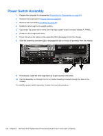
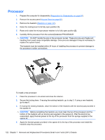
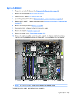
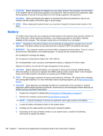
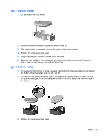
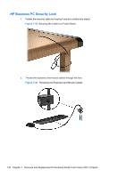
System Board 1. Prepare the computer for disassembly (Preparation for Disassembly on page 84). 2. Remove the access panel (Access Panel on page 85). 3. Remove the front bezel (Front Bezel on page 86). 4. Loosen the plastic cable fasteners (Plastic Wire/Cable Fastener and Clips on page 117). 5. Remove all PCI and PCI Express expansion boards (Removing or Installing an Expansion Card on page 94). 6. Remove all memory modules (Memory on page 88). 7. Disconnect all data and power cables from the system board. 8. Remove the heatsink (Heatsink on page 121). 9. Remove the power supply (Power Supply on page 123). 10. Remove the eight screws that secure the system board to the chassis, slide the board about 1.25 cm (1/2 inch) toward the front of the chassis, and then lift the board out of the chassis. NOTE: HP Pro 3015 shown. System board appearance varies by model. To install the system board, reverse the removal procedure. System Board 125
-
 1
1 -
2
-
3
-
4
-
5
-
6
-
7
-
8
-
9
-
10
-
11
-
12
-
13
-
14
-
15
-
16
-
17
-
18
-
19
-
20
-
21
-
22
-
23
-
24
-
25
-
26
-
27
-
28
-
29
-
30
-
31
-
32
-
33
-
34
-
35
-
36
-
37
-
38
-
39
-
40
-
41
-
42
-
43
-
44
-
45
-
46
-
47
-
48
-
49
-
50
-
51
-
52
-
53
-
54
-
55
-
56
-
57
-
58
-
59
-
60
-
61
-
62
-
63
-
64
-
65
-
66
-
67
-
68
-
69
-
70
-
71
-
72
-
73
-
74
-
75
-
76
-
77
-
78
-
79
-
80
-
81
-
82
-
83
-
84
-
85
-
86
-
87
-
88
-
89
-
90
-
91
-
92
-
93
-
94
-
95
-
96
-
97
-
98
-
99
-
100
-
101
-
102
-
103
-
104
-
105
-
106
-
107
-
108
-
109
-
110
-
111
-
112
-
113
-
114
-
115
-
116
-
117
-
118
-
119
-
120
-
121
-
122
-
123
-
124
-
125
-
126
-
127
-
128
-
129
-
 130
130 -
 131
131 -
 132
132 -
 133
133 -
 134
134 -
 135
135 -
 136
136 -
 137
137 -
 138
138 -
 139
139 -
 140
140 -
141
-
142
-
143
-
144
-
145
-
146
-
147
-
148
-
149
-
150
-
151
-
152
-
153
-
154
-
155
-
156
-
157
-
158
-
159
-
160
-
161
-
162
-
163
-
164
-
165
-
166
-
167
-
168
-
169
-
170
-
171
-
172
-
173
-
174
-
175
-
176
-
177
-
178
-
179
-
180
-
181
-
182
-
183
-
184
-
185
-
186
-
187
-
188
-
189
-
190
-
191
-
192
-
193
-
194
 |
 |