HP ProBook 4540s HP ProBook 4540s Notebook PC HP ProBook 4440s Notebook PC HP - Page 104
Slide the latch toward the left, Position the computer right-side up, with the front toward you.
 |
View all HP ProBook 4540s manuals
Add to My Manuals
Save this manual to your list of manuals |
Page 104 highlights
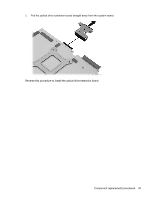
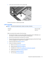
g. Speaker assembly (see Speaker assembly on page 76) h. System board (see System board on page 85) NOTE: The latch mechanism includes a small spring. Note the location of the spring. Remove the latch assembly: 1. Position the computer right-side up, with the front toward you. 2. Slide the latch toward the left (1). 3. Lift the latch from the tab that holds it in place (2). 4. Rotate the latch up and lift it out of the computer (3). Reverse this procedure to install the latch assembly. 96 Chapter 4 Removal and replacement procedures
-
 1
1 -
2
-
3
-
4
-
5
-
6
-
7
-
8
-
9
-
10
-
11
-
12
-
13
-
14
-
15
-
16
-
17
-
18
-
19
-
20
-
21
-
22
-
23
-
24
-
25
-
26
-
27
-
28
-
29
-
30
-
31
-
32
-
33
-
34
-
35
-
36
-
37
-
38
-
39
-
40
-
41
-
42
-
43
-
44
-
45
-
46
-
47
-
48
-
49
-
50
-
51
-
52
-
53
-
54
-
55
-
56
-
57
-
58
-
59
-
60
-
61
-
62
-
63
-
64
-
65
-
66
-
67
-
68
-
69
-
70
-
71
-
72
-
73
-
74
-
75
-
76
-
77
-
78
-
79
-
80
-
81
-
82
-
83
-
84
-
85
-
86
-
87
-
88
-
89
-
90
-
91
-
92
-
93
-
94
-
95
-
96
-
97
-
98
-
 99
99 -
 100
100 -
 101
101 -
 102
102 -
 103
103 -
 104
104 -
 105
105 -
 106
106 -
 107
107 -
 108
108 -
 109
109 -
110
-
111
-
112
-
113
-
114
-
115
-
116
-
117
-
118
-
119
-
120
-
121
-
122
-
123
-
124
-
125
-
126
-
127
-
128
-
129
-
130
-
131
-
132
-
133
-
134
-
135
-
136
-
137
-
138
-
139
-
140
-
141
-
142
-
143
-
144
-
145
 |
 |
g.
Speaker assembly (see
Speaker assembly
on page
76
)
h.
System board (see
System board
on page
85
)
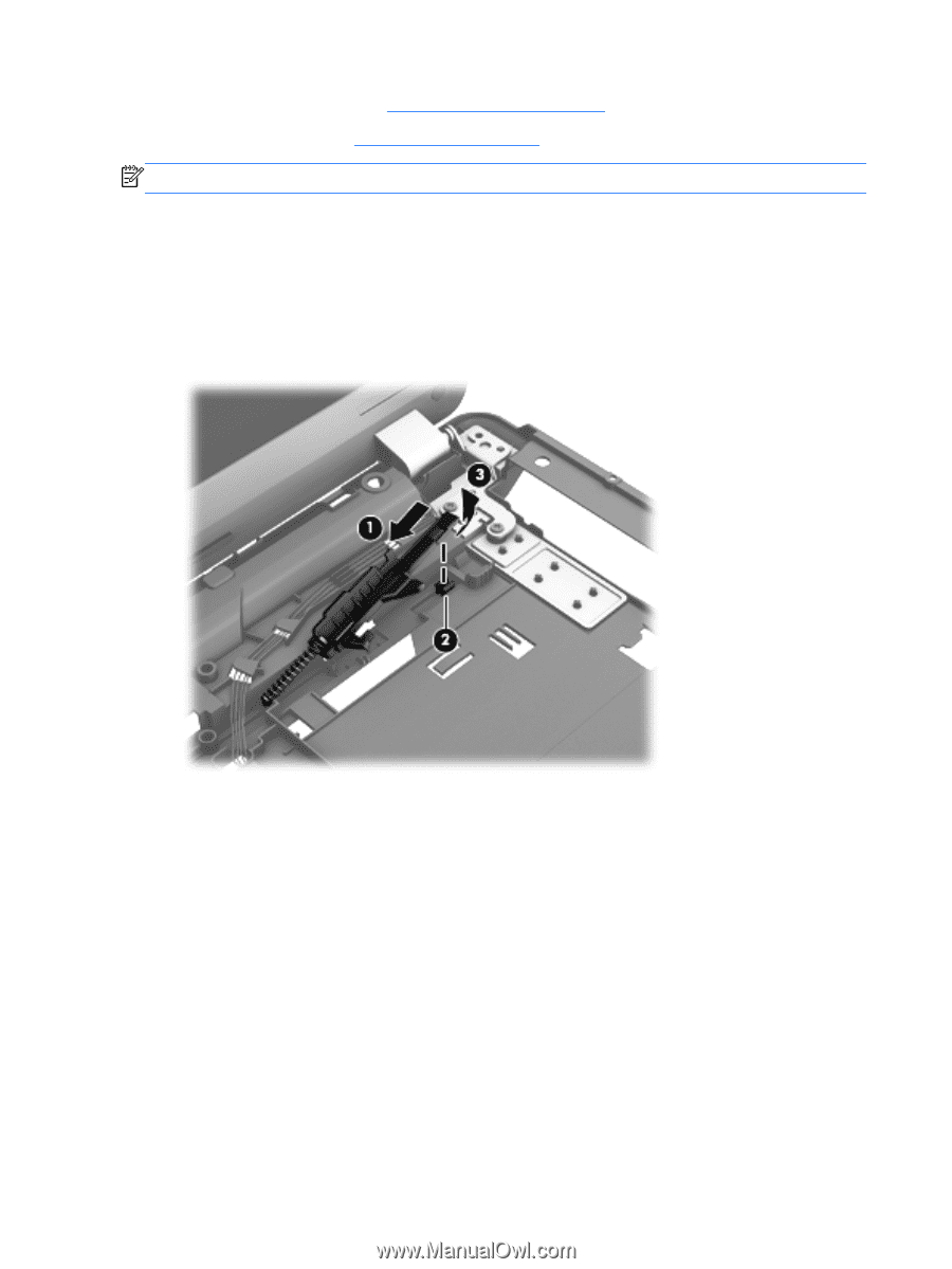
NOTE:
The latch mechanism includes a small spring. Note the location of the spring.
Remove the latch assembly:
1.
Position the computer right-side up, with the front toward you.
2.
Slide the latch toward the left
(1)
.
3.
Lift the latch from the tab that holds it in place
(2)
.
4.
Rotate the latch up and lift it out of the computer
(3)
.
Reverse this procedure to install the latch assembly.
96
Chapter 4
Removal and replacement procedures