HP ProBook 4540s HP ProBook 4540s Notebook PC HP ProBook 4440s Notebook PC HP - Page 111
that secure each display hinge to the display, covers the connector
 |
View all HP ProBook 4540s manuals
Add to My Manuals
Save this manual to your list of manuals |
Page 111 highlights
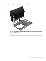
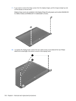
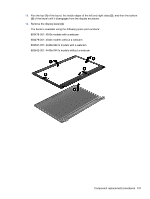
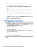
17. Remove the display hinges and panel from the display enclosure. 18. Disconnect the display panel cable by rotating the display enclosure (1), lifting the tape (2) that covers the connector, and disconnecting the cable from the panel (3). 19. Remove the three Phillips PM2.0×3.0 screws (1) that secure each display hinge to the display panel. Component replacement procedures 103
-
 1
1 -
2
-
3
-
4
-
5
-
6
-
7
-
8
-
9
-
10
-
11
-
12
-
13
-
14
-
15
-
16
-
17
-
18
-
19
-
20
-
21
-
22
-
23
-
24
-
25
-
26
-
27
-
28
-
29
-
30
-
31
-
32
-
33
-
34
-
35
-
36
-
37
-
38
-
39
-
40
-
41
-
42
-
43
-
44
-
45
-
46
-
47
-
48
-
49
-
50
-
51
-
52
-
53
-
54
-
55
-
56
-
57
-
58
-
59
-
60
-
61
-
62
-
63
-
64
-
65
-
66
-
67
-
68
-
69
-
70
-
71
-
72
-
73
-
74
-
75
-
76
-
77
-
78
-
79
-
80
-
81
-
82
-
83
-
84
-
85
-
86
-
87
-
88
-
89
-
90
-
91
-
92
-
93
-
94
-
95
-
96
-
97
-
98
-
99
-
100
-
101
-
102
-
103
-
104
-
105
-
 106
106 -
 107
107 -
 108
108 -
 109
109 -
 110
110 -
 111
111 -
 112
112 -
 113
113 -
 114
114 -
 115
115 -
 116
116 -
117
-
118
-
119
-
120
-
121
-
122
-
123
-
124
-
125
-
126
-
127
-
128
-
129
-
130
-
131
-
132
-
133
-
134
-
135
-
136
-
137
-
138
-
139
-
140
-
141
-
142
-
143
-
144
-
145
 |
 |
17.
Remove the display hinges and panel from the display enclosure.
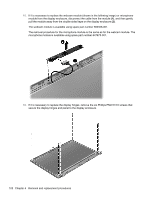
18.
Disconnect the display panel cable by rotating the display enclosure
(1)
, lifting the tape
(2)
that
covers the connector, and disconnecting the cable from the panel
(3)
.
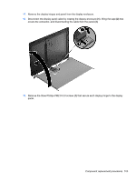
19.
Remove the three Phillips PM2.0×3.0 screws
(1)
that secure each display hinge to the display
panel.
Component replacement procedures
103