HP ProBook 4540s HP ProBook 4540s Notebook PC HP ProBook 4440s Notebook PC HP - Page 94
If disassembling 4440s/4441s models, skip to step 7., When replacing the system board
 |
View all HP ProBook 4540s manuals
Add to My Manuals
Save this manual to your list of manuals |
Page 94 highlights
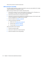
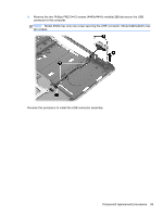
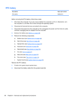
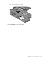
When replacing the system board, be sure to remove the following components from the defective system board and install on the replacement system board: ● Memory module (see Memory modules on page 50) ● SIM (see SIM on page 45) ● WLAN/Bluetooth module (see WLAN/Bluetooth combo card on page 54) ● WWAN module (see WWAN module on page 52) ● Processor (see Processor on page 66) Remove the system board: 1. Position the computer upright with the front toward you. 2. Disconnect the following cables from the system board (model 4440s/4441s shown): . ● (1) Power cable ● (2) Display cable ● (3) Battery connector cable ● (4) USB connector cable 3. If disassembling 4440s/4441s models, skip to step 7. 4. For model 4540s, remove the three Phillips PM2.5×4.5 screws (1) that secure the system board to the computer. Note that two of the screws secure the optical drive connector board and hard drive connector board. 5. Disconnect the display cable from the system board (if necessary). 86 Chapter 4 Removal and replacement procedures
-
 1
1 -
2
-
3
-
4
-
5
-
6
-
7
-
8
-
9
-
10
-
11
-
12
-
13
-
14
-
15
-
16
-
17
-
18
-
19
-
20
-
21
-
22
-
23
-
24
-
25
-
26
-
27
-
28
-
29
-
30
-
31
-
32
-
33
-
34
-
35
-
36
-
37
-
38
-
39
-
40
-
41
-
42
-
43
-
44
-
45
-
46
-
47
-
48
-
49
-
50
-
51
-
52
-
53
-
54
-
55
-
56
-
57
-
58
-
59
-
60
-
61
-
62
-
63
-
64
-
65
-
66
-
67
-
68
-
69
-
70
-
71
-
72
-
73
-
74
-
75
-
76
-
77
-
78
-
79
-
80
-
81
-
82
-
83
-
84
-
85
-
86
-
87
-
88
-
 89
89 -
 90
90 -
 91
91 -
 92
92 -
 93
93 -
 94
94 -
 95
95 -
 96
96 -
 97
97 -
 98
98 -
 99
99 -
100
-
101
-
102
-
103
-
104
-
105
-
106
-
107
-
108
-
109
-
110
-
111
-
112
-
113
-
114
-
115
-
116
-
117
-
118
-
119
-
120
-
121
-
122
-
123
-
124
-
125
-
126
-
127
-
128
-
129
-
130
-
131
-
132
-
133
-
134
-
135
-
136
-
137
-
138
-
139
-
140
-
141
-
142
-
143
-
144
-
145
 |
 |