HP ProBook 4540s HP ProBook 4540s Notebook PC HP ProBook 4440s Notebook PC HP - Page 90
USB connector assembly, Top cover see
 |
View all HP ProBook 4540s manuals
Add to My Manuals
Save this manual to your list of manuals |
Page 90 highlights
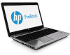
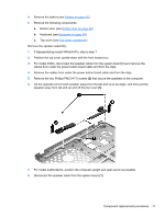
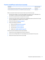
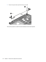
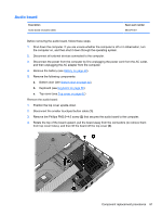
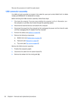
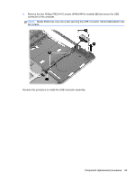
Reverse this procedure to install the audio board. USB connector assembly The USB connector assembly is included in the Cable Kit, spare part number 683477-001 for 4540s models and 683640-001 for 4440s/4441s models. Before removing the USB connector assembly, follow these steps: 1. Shut down the computer. If you are unsure whether the computer is off or in Hibernation, turn the computer on, and then shut it down through the operating system. 2. Disconnect all external devices connected to the computer. 3. Disconnect the power from the computer by first unplugging the power cord from the AC outlet, and then unplugging the AC adapter from the computer. 4. Remove the battery (see Battery on page 42). 5. Remove the following components: a. Bottom door (see Bottom door on page 44). b. Keyboard (see Keyboard on page 56) c. Top cover (see Top cover on page 67) Remove the USB connector assembly: 1. Position the computer upright. 2. Disconnect the cable from the system board (1). 3. Remove the cables from the routing path (2). 82 Chapter 4 Removal and replacement procedures
-
 1
1 -
2
-
3
-
4
-
5
-
6
-
7
-
8
-
9
-
10
-
11
-
12
-
13
-
14
-
15
-
16
-
17
-
18
-
19
-
20
-
21
-
22
-
23
-
24
-
25
-
26
-
27
-
28
-
29
-
30
-
31
-
32
-
33
-
34
-
35
-
36
-
37
-
38
-
39
-
40
-
41
-
42
-
43
-
44
-
45
-
46
-
47
-
48
-
49
-
50
-
51
-
52
-
53
-
54
-
55
-
56
-
57
-
58
-
59
-
60
-
61
-
62
-
63
-
64
-
65
-
66
-
67
-
68
-
69
-
70
-
71
-
72
-
73
-
74
-
75
-
76
-
77
-
78
-
79
-
80
-
81
-
82
-
83
-
84
-
 85
85 -
 86
86 -
 87
87 -
 88
88 -
 89
89 -
 90
90 -
 91
91 -
 92
92 -
 93
93 -
 94
94 -
 95
95 -
96
-
97
-
98
-
99
-
100
-
101
-
102
-
103
-
104
-
105
-
106
-
107
-
108
-
109
-
110
-
111
-
112
-
113
-
114
-
115
-
116
-
117
-
118
-
119
-
120
-
121
-
122
-
123
-
124
-
125
-
126
-
127
-
128
-
129
-
130
-
131
-
132
-
133
-
134
-
135
-
136
-
137
-
138
-
139
-
140
-
141
-
142
-
143
-
144
-
145
 |
 |