HP ProLiant DL288 HP ProLiant DL288 G6 Server Software Configuration Guide - Page 42
POST-related troubleshooting, Invalid or Unknown SKU/Chassis ID
 |
View all HP ProLiant DL288 manuals
Add to My Manuals
Save this manual to your list of manuals |
Page 42 highlights
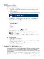
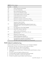
Table 23 POST Error Messages Error code 198 601 605 611 612 613 620 621 622 Description Processor QPI speed mismatch detected. Error: BMC Not Responding BMC Has Detected Fatal Hardware Error Internal User Area Of BMC FRU Corrupted Controller Update 'boot block' Firmware Corrupted Controller Operational Firmware Corrupted Non-Redundant Fan Failure or Missing Redundant Fan Configuration, One Fan Failure or Missing Redundant Fan Configuration, Multiple Fans Failure or Missing Temperature Violation Detected Waiting 5 minutes for system to cool 623 Press ESC Key to resume booting without waiting for the system to cool Warning: Pressing ESC is NOT recommended as the system may shutdown unexpectedly 624 Power Supply Failure or Power Supply Unplugged 626 Update SDRR/Configuration Image failed Invalid or Unknown SKU/Chassis ID 627 Please check Front panel, System ID Jumper or Riser card Press F1 to Continue 628 Redundant Power Supply Mismatch 701 Insufficient Runtime space for MPS data.!!. System may operate in PIC or Non-MPS mode. No enough APIC ID in range 0-0Fh can be assigned to IO APICs. 702 (Re-assigning CPUs' local APIC ID may solve this issue) MPS Table is not built! System may operate in PIC or Non-MPS mode. POST-related troubleshooting Perform the following procedures when POST fails to run, error messages are displayed. If the POST failure is during a routine boot up, verify the following conditions: • All external cables and power cables are firmly plugged in. • The power outlet to which the server is connected is working. • The server and monitor are both turned on. The bicolor power status LED indicator on the ear must be green. • The monitor's contrast and brightness settings are correct. • All internal cables are properly connected and all boards firmly seated. • The processor is fully seated in its socket on the system board. • The heat sink assembly is properly installed on top of the processor. System BIOS configuration 42
-
 1
1 -
2
-
3
-
4
-
5
-
6
-
7
-
8
-
9
-
10
-
11
-
12
-
13
-
14
-
15
-
16
-
17
-
18
-
19
-
20
-
21
-
22
-
23
-
24
-
25
-
26
-
27
-
28
-
29
-
30
-
31
-
32
-
33
-
34
-
35
-
36
-
 37
37 -
 38
38 -
 39
39 -
 40
40 -
 41
41 -
 42
42 -
 43
43 -
 44
44 -
 45
45 -
 46
46 -
 47
47 -
48
-
49
-
50
 |
 |