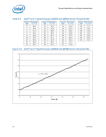
Intel Q9400S Data Sheet - Page 85
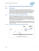
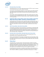
Conceptual Fan Control Diagram on PECI-Based Platforms
 |
UPC - 735858207973
View all Intel Q9400S manuals
Add to My Manuals
Save this manual to your list of manuals |
Page 85 highlights
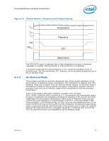
Thermal Specifications and Design Considerations 5.3 Platform Environment Control Interface (PECI) 5.3.1 Introduction PECI offers an interface for thermal monitoring of Intel processor and chipset components. It uses a single wire, thus alleviating routing congestion issues. PECI uses CRC checking on the host side to ensure reliable transfers between the host and client devices. Also, data transfer speeds across the PECI interface are negotiable within a wide range (2Kbps to 2Mbps). The PECI interface on the processor is disabled by default and must be enabled through BIOS. More information can be found in the Platform Environment Control Interface (PECI) Specification. 5.3.1.1 TCONTROL and TCC activation on PECI-Based Systems Fan speed control solutions based on PECI utilize a TCONTROL value stored in the processor IA32_TEMPERATURE_TARGET MSR. The TCONTROL MSR uses the same offset temperature format as PECI though it contains no sign bit. Thermal management devices should infer the TCONTROL value as negative. Thermal management algorithms should utilize the relative temperature value delivered over PECI in conjunction with the TCONTROL MSR value to control or optimize fan speeds. Figure 5-7 shows a conceptual fan control diagram using PECI temperatures. The relative temperature value reported over PECI represents the delta below the onset of thermal control circuit (TCC) activation as indicated by PROCHOT# assertions. As the temperature approaches TCC activation, the PECI value approaches zero. TCC activates at a PECI count of zero. Figure 5-7. Conceptual Fan Control Diagram on PECI-Based Platforms Datasheet 85
-
 1
1 -
2
-
3
-
4
-
5
-
6
-
7
-
8
-
9
-
10
-
11
-
12
-
13
-
14
-
15
-
16
-
17
-
18
-
19
-
20
-
21
-
22
-
23
-
24
-
25
-
26
-
27
-
28
-
29
-
30
-
31
-
32
-
33
-
34
-
35
-
36
-
37
-
38
-
39
-
40
-
41
-
42
-
43
-
44
-
45
-
46
-
47
-
48
-
49
-
50
-
51
-
52
-
53
-
54
-
55
-
56
-
57
-
58
-
59
-
60
-
61
-
62
-
63
-
64
-
65
-
66
-
67
-
68
-
69
-
70
-
71
-
72
-
73
-
74
-
75
-
76
-
77
-
78
-
79
-
 80
80 -
 81
81 -
 82
82 -
 83
83 -
 84
84 -
 85
85 -
 86
86 -
 87
87 -
 88
88 -
 89
89 -
 90
90 -
91
-
92
-
93
-
94
-
95
-
96
-
97
-
98
-
99
-
100
-
101
-
102
-
103
-
104
 |
 |
