Intel Q9400S Data Sheet - Page 98
Variable Speed Fan
 |
UPC - 735858207973
View all Intel Q9400S manuals
Add to My Manuals
Save this manual to your list of manuals |
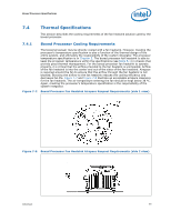
Page 98 highlights
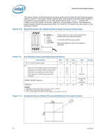
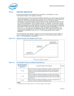
Boxed Processor Specifications 7.4.2 Variable Speed Fan If the boxed processor fan heatsink 4-pin connector is connected to a 3-pin motherboard header it will operate as follows: The boxed processor fan will operate at different speeds over a short range of internal chassis temperatures. This allows the processor fan to operate at a lower speed and noise level, while internal chassis temperatures are low. If internal chassis temperature increases beyond a lower set point, the fan speed will rise linearly with the internal temperature until the higher set point is reached. At that point, the fan speed is at its maximum. As fan speed increases, so does fan noise levels. Systems should be designed to provide adequate air around the boxed processor fan heatsink that remains cooler then lower set point. These set points, represented in Figure 7-9 and Table 7-2, can vary by a few degrees from fan heatsink to fan heatsink. The internal chassis temperature should be kept below 38 ºC. Meeting the processor's temperature specification (see Chapter 5) is the responsibility of the system integrator. The motherboard must supply a constant +12 V to the processor's power header to ensure proper operation of the variable speed fan for the boxed processor. Refer to Table 7-1 for the specific requirements. Figure 7-9. Boxed Processor Fan Heatsink Set Points Increasing Fan Speed & Noise Higher Set Point Highest Noise Level Lower Set Point Lowest Noise Level X Y Z Internal Chassis Temperature (Degrees C) Table 7-2. Fan Heatsink Power and Signal Specifications Boxed Processor Fan Heatsink Set Point (°C) Boxed Processor Fan Speed Notes X ≤ 30 When the internal chassis temperature is below or equal to this set point, the fan operates at its lowest speed. Recommended 1 maximum internal chassis temperature for nominal operating environment. Y = 35 When the internal chassis temperature is at this point, the fan operates between its lowest and highest speeds. Recommended maximum internal chassis temperature for worst-case operating - environment. Z ≥ 39 When the internal chassis temperature is above or equal to this set point, the fan operates at its highest speed. - NOTES: 1. Set point variance is approximately ±1 °C from fan heatsink to fan heatsink. 100 Datasheet
-
 1
1 -
2
-
3
-
4
-
5
-
6
-
7
-
8
-
9
-
10
-
11
-
12
-
13
-
14
-
15
-
16
-
17
-
18
-
19
-
20
-
21
-
22
-
23
-
24
-
25
-
26
-
27
-
28
-
29
-
30
-
31
-
32
-
33
-
34
-
35
-
36
-
37
-
38
-
39
-
40
-
41
-
42
-
43
-
44
-
45
-
46
-
47
-
48
-
49
-
50
-
51
-
52
-
53
-
54
-
55
-
56
-
57
-
58
-
59
-
60
-
61
-
62
-
63
-
64
-
65
-
66
-
67
-
68
-
69
-
70
-
71
-
72
-
73
-
74
-
75
-
76
-
77
-
78
-
79
-
80
-
81
-
82
-
83
-
84
-
85
-
86
-
87
-
88
-
89
-
90
-
91
-
92
-
 93
93 -
 94
94 -
 95
95 -
 96
96 -
 97
97 -
 98
98 -
 99
99 -
 100
100 -
 101
101 -
 102
102 -
 103
103 -
104
 |
 |
