LG 32LP1D Owners Manual - Page 102
External, Control, Device, Setup
 |
UPC - 719192168534
View all LG 32LP1D manuals
Add to My Manuals
Save this manual to your list of manuals |
Page 102 highlights
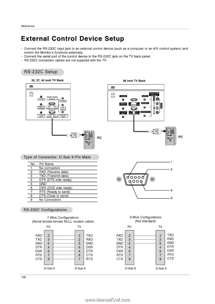
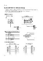
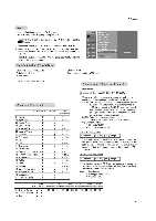
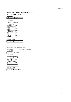
Reference External Control Device Setup - Connect the RS-232C input jack to an external control device (such as a computer or an AN control system) and control the Monitor's functions externally. - Connect the serial port of the control device to the RS-232C jack on the TV back panel. - RS-232C connection cables are not supplied with the TV. RS-232C Setup 32, 37, 42 inch TV Back 26 inch TV Back (7-.) AC IN • (NANA I • DIGITAL AIX.* (OPTICAL( I- • I CUM", - • • • DOM. /WM AC IN U'OPTICAL Kum RCNIO ILAAL.,21 - • PC AAJC.0 -PUT • E te. ■ I PC IA* • • Type of Connector; D -Sub 9 -Pin Male No. Pin Name 1 No connection 2 RXD (Receive data) 3 TXD (Transmit data) 4 DTR (DTE side ready) 5 GND 6 DSR (DCE side read' 7 RTS (Ready to send) 8 CTS (Clear to send) 9 No Connection RS -232C Configurations 7-Wire Configurations (Serial female-female NULL modem cable) PC TV RXD 2 TXD 3 GND 5 DTR 4 DSR 6 RTS 7 CTS 8 3 TXD 2 RXD 5 GND 6 DSR 4 DTR 8 CTS 7 RTS D-Sub 9 D-Sub 9 102 PC 000 00 9 6 3-Wire Configurations (Not standard) PC TV RXD 2 TXD 3 GND 5 DTR 4 DSR 6 RTS 7 CTS 8 3 TXD 2 RXD 5 GND 4 DTR 6 DSR 7 RTS 8 CTS D-Sub 9 D-Sub 9
-
 1
1 -
2
-
3
-
4
-
5
-
6
-
7
-
8
-
9
-
10
-
11
-
12
-
13
-
14
-
15
-
16
-
17
-
18
-
19
-
20
-
21
-
22
-
23
-
24
-
25
-
26
-
27
-
28
-
29
-
30
-
31
-
32
-
33
-
34
-
35
-
36
-
37
-
38
-
39
-
40
-
41
-
42
-
43
-
44
-
45
-
46
-
47
-
48
-
49
-
50
-
51
-
52
-
53
-
54
-
55
-
56
-
57
-
58
-
59
-
60
-
61
-
62
-
63
-
64
-
65
-
66
-
67
-
68
-
69
-
70
-
71
-
72
-
73
-
74
-
75
-
76
-
77
-
78
-
79
-
80
-
81
-
82
-
83
-
84
-
85
-
86
-
87
-
88
-
89
-
90
-
91
-
92
-
93
-
94
-
95
-
96
-
 97
97 -
 98
98 -
 99
99 -
 100
100 -
 101
101 -
 102
102 -
 103
103 -
 104
104 -
 105
105 -
 106
106 -
 107
107 -
108
-
109
-
110
-
111
-
112
-
113
-
114
-
115
-
116
 |
 |