LG 32LP1D Owners Manual - Page 22
Audionideo
 |
UPC - 719192168534
View all LG 32LP1D manuals
Add to My Manuals
Save this manual to your list of manuals |
Page 22 highlights
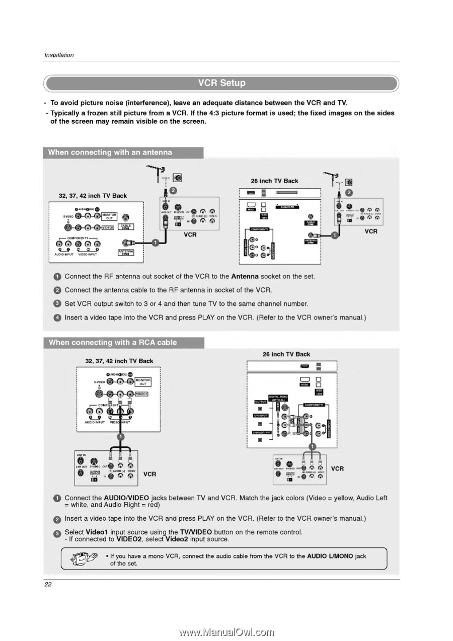
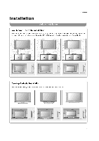
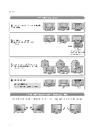
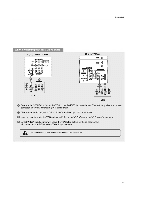
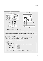
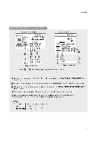
Installation - To avoid picture noise (interference), leave an adequate distance between the VCR and TV. - Typically a frozen still picture from a VCR. If the 4:3 picture format is used; the fixed images on the sides of the screen may remain visible on the screen. When connecting with an antenna 32, 37, 42 inch TV Back • 110-..0, 0n. COMPONENT, --, 06 7).M0 9_9 9 2 510 AMMO INPUT VIDEO INPUT IPA 2!9 41. MI OM ®o Fr.i11 1 ak " " - az Pn 7;;, VCR a • imzcm O )C IME 26 inch TV Back N CO G G • Connect the RF antenna out socket of the VCR to the Antenna socket on the set. • Connect the antenna cable to the RF antenna in socket of the VCR. • Set VCR output switch to 3 or 4 and then tune TV to the same channel number. • Insert a video tape into the VCR and press PLAY on the VCR. (Refer to the VCR owner's manual.) When connecting with a RCA cable 32, 37, 42 inch TV Back • O IAOMTOR OUT 4040( IDE01 r- COMP EN AUDIO INPUT VIDE PUT 26 inch TV Back ■ ■ IIffN 0 0 MR OUT sJADI0 OUT • . or) MOO (L) MOO W 761 (..) Ks) VCR if • rem Ow A ir .9 o 6,0•60.1. 0 .00, VCR • Connect the AUDIONIDEO jacks between TV and VCR. Match the jack colors (Video = yellow, Audio Left white, and Audio Right = red) • Insert a video tape into the VCR and press PLAY on the VCR. (Refer to the VCR owner's manual.) Select Videol input source using the TVNIDEO button on the remote control. - If connected to VIDEO2, select Video2 input source. 0, • If you have a mono VCR, connect the audio cable from the VCR to the AUDIO L/MONO jack of the set. 22
-
 1
1 -
2
-
3
-
4
-
5
-
6
-
7
-
8
-
9
-
10
-
11
-
12
-
13
-
14
-
15
-
16
-
 17
17 -
 18
18 -
 19
19 -
 20
20 -
 21
21 -
 22
22 -
 23
23 -
 24
24 -
 25
25 -
 26
26 -
 27
27 -
28
-
29
-
30
-
31
-
32
-
33
-
34
-
35
-
36
-
37
-
38
-
39
-
40
-
41
-
42
-
43
-
44
-
45
-
46
-
47
-
48
-
49
-
50
-
51
-
52
-
53
-
54
-
55
-
56
-
57
-
58
-
59
-
60
-
61
-
62
-
63
-
64
-
65
-
66
-
67
-
68
-
69
-
70
-
71
-
72
-
73
-
74
-
75
-
76
-
77
-
78
-
79
-
80
-
81
-
82
-
83
-
84
-
85
-
86
-
87
-
88
-
89
-
90
-
91
-
92
-
93
-
94
-
95
-
96
-
97
-
98
-
99
-
100
-
101
-
102
-
103
-
104
-
105
-
106
-
107
-
108
-
109
-
110
-
111
-
112
-
113
-
114
-
115
-
116
 |
 |