Lenovo ThinkCentre M92z Hardware Maintenance Manual - ThinkCentre M92z (type 3 - Page 113
Carefully remove the four screws from the system board to avoid any possible damage to
 |
View all Lenovo ThinkCentre M92z manuals
Add to My Manuals
Save this manual to your list of manuals |
Page 113 highlights
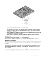
To replace the heat sink and fan assembly for GPU, do the following: 1. Remove all media from the drives and turn off all attached devices and the computer. Then, disconnect all power cords from electrical outlets and disconnect all cables that are connected to the computer. 2. Place a soft, clean towel or cloth on the desk or surface. Hold the sides of your computer and gently lay it down so that the screen is against the surface and the cover is facing up. 3. Remove the computer cover. See "Removing the computer cover" on page 83. 4. Locate the heat sink and fan assembly for GPU. See "Locating major FRUs and CRUs (for models with the 20-inch display)" on page 73 or "Locating major FRUs and CRUs (for models with the 23-inch display)" on page 76. 5. Note the routing of the GPU fan cable and then disconnect the GPU fan cable from the system board. 6. Follow this sequence to remove the four screws that secure the heat sink and fan assembly for GPU to the system board: a. Partially remove screw 1 , then fully remove screw 2 , and then fully remove screw 1 . b. Partially remove screw 3 , then fully remove screw 4 , and then fully remove screw 3 . Note: Carefully remove the four screws from the system board to avoid any possible damage to the system board. The four screws cannot be removed from the heat sink and fan assembly for GPU. Figure 38. Removing the heat sink and fan assembly for GPU 7. Lift the failing heat sink and fan assembly for GPU off the system board. Notes: a. You might have to gently twist the heat sink and fan assembly for GPU to free it from the microprocessor. b. Do not touch the thermal grease while handling the heat sink and fan assembly for GPU. 8. Position the new heat sink and fan assembly for GPU on the system board so that the four screws are aligned with the corresponding holes in the system board. Chapter 9. Replacing FRUs 109
-
 1
1 -
2
-
3
-
4
-
5
-
6
-
7
-
8
-
9
-
10
-
11
-
12
-
13
-
14
-
15
-
16
-
17
-
18
-
19
-
20
-
21
-
22
-
23
-
24
-
25
-
26
-
27
-
28
-
29
-
30
-
31
-
32
-
33
-
34
-
35
-
36
-
37
-
38
-
39
-
40
-
41
-
42
-
43
-
44
-
45
-
46
-
47
-
48
-
49
-
50
-
51
-
52
-
53
-
54
-
55
-
56
-
57
-
58
-
59
-
60
-
61
-
62
-
63
-
64
-
65
-
66
-
67
-
68
-
69
-
70
-
71
-
72
-
73
-
74
-
75
-
76
-
77
-
78
-
79
-
80
-
81
-
82
-
83
-
84
-
85
-
86
-
87
-
88
-
89
-
90
-
91
-
92
-
93
-
94
-
95
-
96
-
97
-
98
-
99
-
100
-
101
-
102
-
103
-
104
-
105
-
106
-
107
-
 108
108 -
 109
109 -
 110
110 -
 111
111 -
 112
112 -
 113
113 -
 114
114 -
 115
115 -
 116
116 -
 117
117 -
 118
118 -
119
-
120
-
121
-
122
-
123
-
124
-
125
-
126
-
127
-
128
-
129
-
130
-
131
-
132
-
133
-
134
-
135
-
136
-
137
-
138
-
139
-
140
-
141
-
142
-
143
-
144
 |
 |
