Lenovo ThinkCentre M92z Hardware Maintenance Manual - ThinkCentre M92z (type 3 - Page 121
Connect the new LCD cables to the display connectors on the system board and the converter board.
 |
View all Lenovo ThinkCentre M92z manuals
Add to My Manuals
Save this manual to your list of manuals |
Page 121 highlights
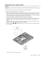
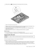
9. Connect the new LCD cables to the display connectors on the system board and the converter board. See "Locating parts on the system board" on page 79. 10. Align the screw holes in the new LCD panel with the corresponding ones in the LCD bracket. To avoid any damage when installing the LCD panel, follow the below exact sequence to install the four screws 1 , 2 , 3 , and 4 to secure the LCD panel. Figure 46. Installing the LCD panel Attention: Do not overtighten the screws. Overtightening the screws might damage the LCD panel. 11. Position the LCD bracket over the front bezel, ensure that the screw holes in the LCD bracket align with the mounting stands in the front bezel. 12. Reinstall all the 13 screws to secure the LCD bracket to the front bezel. Figure 47. Reinstalling the LCD bracket Chapter 9. Replacing FRUs 117
-
 1
1 -
2
-
3
-
4
-
5
-
6
-
7
-
8
-
9
-
10
-
11
-
12
-
13
-
14
-
15
-
16
-
17
-
18
-
19
-
20
-
21
-
22
-
23
-
24
-
25
-
26
-
27
-
28
-
29
-
30
-
31
-
32
-
33
-
34
-
35
-
36
-
37
-
38
-
39
-
40
-
41
-
42
-
43
-
44
-
45
-
46
-
47
-
48
-
49
-
50
-
51
-
52
-
53
-
54
-
55
-
56
-
57
-
58
-
59
-
60
-
61
-
62
-
63
-
64
-
65
-
66
-
67
-
68
-
69
-
70
-
71
-
72
-
73
-
74
-
75
-
76
-
77
-
78
-
79
-
80
-
81
-
82
-
83
-
84
-
85
-
86
-
87
-
88
-
89
-
90
-
91
-
92
-
93
-
94
-
95
-
96
-
97
-
98
-
99
-
100
-
101
-
102
-
103
-
104
-
105
-
106
-
107
-
108
-
109
-
110
-
111
-
112
-
113
-
114
-
115
-
 116
116 -
 117
117 -
 118
118 -
 119
119 -
 120
120 -
 121
121 -
 122
122 -
 123
123 -
 124
124 -
 125
125 -
 126
126 -
127
-
128
-
129
-
130
-
131
-
132
-
133
-
134
-
135
-
136
-
137
-
138
-
139
-
140
-
141
-
142
-
143
-
144
 |
 |
