Lenovo ThinkCentre M92z Hardware Maintenance Manual - ThinkCentre M92z (type 3 - Page 124
The failing system board must be returned with a microprocessor socket cover to protect the pins during
 |
View all Lenovo ThinkCentre M92z manuals
Add to My Manuals
Save this manual to your list of manuals |
Page 124 highlights
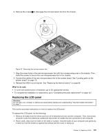
Figure 49. Reinstalling the system board 18. Reinstall the heat sink and fan assembly for GPU if your computer has one. See "Replacing the heat sink and fan assembly for GPU" on page 108. 19. Reinstall the card reader if your computer has one. See "Replacing the card reader" on page 106. 20. Reinstall the ExpressCard if your computer has one. See "Replacing the ExpressCard" on page 107. 21. Reinstall the WiFi card if your computer has one. See "Replacing the WiFi card" on page 102. 22. Reinstall the battery. See "Replacing the battery" on page 111. 23. Reinstall the memory modules. See "Installing or replacing a memory module" on page 86. 24. Reinstall the microprocessor. See "Replacing the microprocessor" on page 94. 25. Reinstall the heat sink. See "Replacing the heat sink" on page 93. 26. Reinstall the rear I/O assembly. See "Removing and reinstalling the rear I/O assembly" on page 85. 27. Reconnect all cables that were disconnected from the system board. See "Locating parts on the system board" on page 79. 28. Go to "Completing the parts replacement" on page 127. The failing system board must be returned with a microprocessor socket cover to protect the pins during shipping and handling. To install the microprocessor socket cover, do the following: 1. Release the lever securing the microprocessor retainer and open the retainer to access the microprocessor. 2. Grasp the microprocessor on the sides and lift it straight up and out of the socket. Do not touch the contacts on the microprocessor socket. 120 ThinkCentre Hardware Maintenance Manual
-
 1
1 -
2
-
3
-
4
-
5
-
6
-
7
-
8
-
9
-
10
-
11
-
12
-
13
-
14
-
15
-
16
-
17
-
18
-
19
-
20
-
21
-
22
-
23
-
24
-
25
-
26
-
27
-
28
-
29
-
30
-
31
-
32
-
33
-
34
-
35
-
36
-
37
-
38
-
39
-
40
-
41
-
42
-
43
-
44
-
45
-
46
-
47
-
48
-
49
-
50
-
51
-
52
-
53
-
54
-
55
-
56
-
57
-
58
-
59
-
60
-
61
-
62
-
63
-
64
-
65
-
66
-
67
-
68
-
69
-
70
-
71
-
72
-
73
-
74
-
75
-
76
-
77
-
78
-
79
-
80
-
81
-
82
-
83
-
84
-
85
-
86
-
87
-
88
-
89
-
90
-
91
-
92
-
93
-
94
-
95
-
96
-
97
-
98
-
99
-
100
-
101
-
102
-
103
-
104
-
105
-
106
-
107
-
108
-
109
-
110
-
111
-
112
-
113
-
114
-
115
-
116
-
117
-
118
-
 119
119 -
 120
120 -
 121
121 -
 122
122 -
 123
123 -
 124
124 -
 125
125 -
 126
126 -
 127
127 -
 128
128 -
 129
129 -
130
-
131
-
132
-
133
-
134
-
135
-
136
-
137
-
138
-
139
-
140
-
141
-
142
-
143
-
144
 |
 |
