Lenovo ThinkCentre M92z Hardware Maintenance Manual - ThinkCentre M92z (type 3 - Page 98
Replacing the microprocessor, Partially tighten screw
 |
View all Lenovo ThinkCentre M92z manuals
Add to My Manuals
Save this manual to your list of manuals |
Page 98 highlights
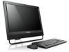
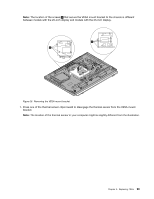
b. Partially remove screw 3 , then fully remove screw 4 , and then fully remove screw 3 . Note: Carefully remove the four screws from the system board to avoid any possible damage to the system board. The four screws cannot be removed from the heat sink. Figure 23. Removing the heat sink 6. Remove the failing heat sink off the system board. Notes: a. You might have to gently twist the heat sink to free it from the microprocessor. b. Do not touch the thermal grease while handling the heat sink. 7. Position the new heat sink on the system board so that the four screws are aligned with the corresponding holes in the system board. 8. Follow this sequence to install the four screws to secure the heat sink, as shown in Figure 23 "Removing the heat sink" on page 94. a. Partially tighten screw 1 , then fully tighten screw 2 , and then fully tighten screw 1 . b. Partially tighten screw 3 , then fully tighten screw 4 , and then fully tighten screw 3 . What to do next: • To work with another piece of hardware, go to the appropriate section. • To complete the installation or replacement, go to "Completing the parts replacement" on page 127. Replacing the microprocessor Attention: Do not open your computer or attempt any repair before reading and understanding "Important Safety Information" on page 1. 94 ThinkCentre Hardware Maintenance Manual
-
 1
1 -
2
-
3
-
4
-
5
-
6
-
7
-
8
-
9
-
10
-
11
-
12
-
13
-
14
-
15
-
16
-
17
-
18
-
19
-
20
-
21
-
22
-
23
-
24
-
25
-
26
-
27
-
28
-
29
-
30
-
31
-
32
-
33
-
34
-
35
-
36
-
37
-
38
-
39
-
40
-
41
-
42
-
43
-
44
-
45
-
46
-
47
-
48
-
49
-
50
-
51
-
52
-
53
-
54
-
55
-
56
-
57
-
58
-
59
-
60
-
61
-
62
-
63
-
64
-
65
-
66
-
67
-
68
-
69
-
70
-
71
-
72
-
73
-
74
-
75
-
76
-
77
-
78
-
79
-
80
-
81
-
82
-
83
-
84
-
85
-
86
-
87
-
88
-
89
-
90
-
91
-
92
-
 93
93 -
 94
94 -
 95
95 -
 96
96 -
 97
97 -
 98
98 -
 99
99 -
 100
100 -
 101
101 -
 102
102 -
 103
103 -
104
-
105
-
106
-
107
-
108
-
109
-
110
-
111
-
112
-
113
-
114
-
115
-
116
-
117
-
118
-
119
-
120
-
121
-
122
-
123
-
124
-
125
-
126
-
127
-
128
-
129
-
130
-
131
-
132
-
133
-
134
-
135
-
136
-
137
-
138
-
139
-
140
-
141
-
142
-
143
-
144
 |
 |
