Lenovo ThinkPad Edge E135 (English) User Guide - Page 85
Attach the cover, and pivot it downwards
 |
View all Lenovo ThinkPad Edge E135 manuals
Add to My Manuals
Save this manual to your list of manuals |
Page 85 highlights
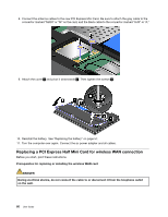
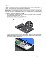
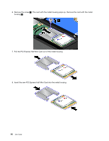
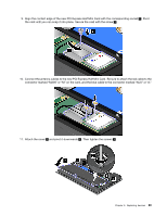
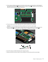
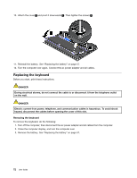
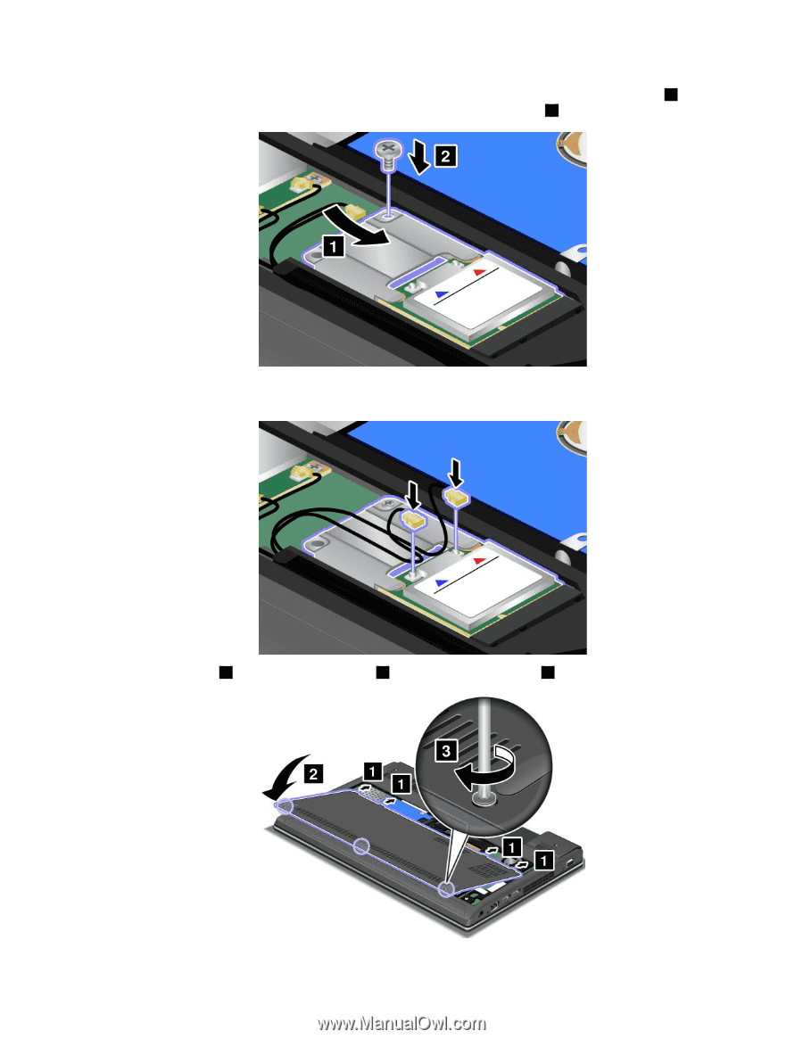
9. Align the contact edge of the new PCI Express Half Mini Card with the corresponding socket 1 . Pivot the card until you can snap it into place. Secure the card with the screw 2 . 10. Connect the antenna cables to the new PCI Express Half Mini Card. Be sure to attach the red cable to the connector marked "MAIN" or "M" on the card, and the blue cable to the connector marked "AUX" or "A." 11. Attach the cover 1 and pivot it downwards 2 . Then tighten the screws 3 . Chapter 6. Replacing devices 69
-
 1
1 -
2
-
3
-
4
-
5
-
6
-
7
-
8
-
9
-
10
-
11
-
12
-
13
-
14
-
15
-
16
-
17
-
18
-
19
-
20
-
21
-
22
-
23
-
24
-
25
-
26
-
27
-
28
-
29
-
30
-
31
-
32
-
33
-
34
-
35
-
36
-
37
-
38
-
39
-
40
-
41
-
42
-
43
-
44
-
45
-
46
-
47
-
48
-
49
-
50
-
51
-
52
-
53
-
54
-
55
-
56
-
57
-
58
-
59
-
60
-
61
-
62
-
63
-
64
-
65
-
66
-
67
-
68
-
69
-
70
-
71
-
72
-
73
-
74
-
75
-
76
-
77
-
78
-
79
-
 80
80 -
 81
81 -
 82
82 -
 83
83 -
 84
84 -
 85
85 -
 86
86 -
 87
87 -
 88
88 -
 89
89 -
 90
90 -
91
-
92
-
93
-
94
-
95
-
96
-
97
-
98
-
99
-
100
-
101
-
102
-
103
-
104
-
105
-
106
-
107
-
108
-
109
-
110
-
111
-
112
-
113
-
114
-
115
-
116
-
117
-
118
-
119
-
120
-
121
-
122
-
123
-
124
-
125
-
126
-
127
-
128
-
129
-
130
-
131
-
132
-
133
-
134
-
135
-
136
-
137
-
138
-
139
-
140
-
141
-
142
-
143
-
144
-
145
-
146
-
147
-
148
-
149
-
150
-
151
-
152
-
153
-
154
-
155
-
156
-
157
-
158
 |
 |
9. Align the contact edge of the new PCI Express Half Mini Card with the corresponding socket
1
. Pivot
the card until you can snap it into place. Secure the card with the screw
2
.
10. Connect the antenna cables to the new PCI Express Half Mini Card. Be sure to attach the red cable to the
connector marked “MAIN” or “M” on the card, and the blue cable to the connector marked “AUX” or “A.”
11. Attach the cover
1
and pivot it downwards
2
. Then tighten the screws
3
.
Chapter 6
.
Replacing devices
69