LiftMaster GH GT- Logic 4 Installation Manual
LiftMaster GH Manual
 |
View all LiftMaster GH manuals
Add to My Manuals
Save this manual to your list of manuals |
LiftMaster GH manual content summary:
- LiftMaster GH | GT- Logic 4 Installation Manual - Page 1
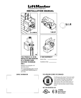
L 4 ogic L3 GH THIS PRODUCT IS TO BE INSTALLED AND SERVICED BY A TRAINED DOOR SYSTEMS TECHNICIAN ONLY. Operators are shipped in C2 operating mode. Visit www.liftmaster.com to locate a professional installing dealer in your area. CONTACT INFORMATION GT 2 YEAR WARRANTY Serial # Box Installation - LiftMaster GH | GT- Logic 4 Installation Manual - Page 2
Life of Operator Feature (Odometer/Cycle Counter) . . . . 36 Brake (If Present 36 How to Order Repair Parts 36 TROUBLESHOOTING 37-40 Diagnostic Chart 37 Troubleshooting Guide 38 Troubleshooting Error Codes 39 Troubleshooting Radio Functionality 40 WIRING DIAGRAMS 41-42 Logic (Ver - LiftMaster GH | GT- Logic 4 Installation Manual - Page 3
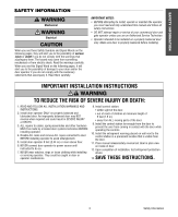
Mechanical CWAWAUARTRINONINNINGG Electrical CWAUATRIONINNG WARNING IMPORTANT NOTES: • BEFORE attempting to install, operate or maintain the operator, you must read and fully understand this manual and follow all safety instructions. WARNING • DO NOT attempt repair or service of your commercial door - LiftMaster GH | GT- Logic 4 Installation Manual - Page 4
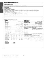
60Hz 4.2 5.6 6.8 8 10 208/230-3Ø, 60Hz 3 3.1 4 6 7 460-3Ø, 60Hz 1.5 1.75 2 3 3.5 575-3Ø, 60Hz 1.3 1.4 1.6 1.8 2.75 Model APT Voltage-Phase 115-1Ø, 60Hz 1/2 HP 11.2 ELECTRICAL TRANSFORMER 24Vac Secondary CONTROL STATION NEMA 3-Button Station Open/Close/Stop w/LED WIRING TYPE C2 - LiftMaster GH | GT- Logic 4 Installation Manual - Page 5
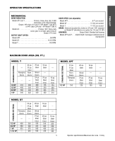
: #41 chain OUTPUT SHAFT SPEED: Model APT 96 RPM Model GT 113.5 RPM Model T 140 RPM DOOR SPEED (not adjustable): Model APT 6-7" per second Model GT 11-12" per second Model T 11-12" per second BRAKE: Solenoid actuated disc brake on 3/4 and 1 HP, standard on Model GT (Available as an option for - LiftMaster GH | GT- Logic 4 Installation Manual - Page 6
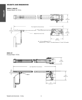
Plus 4 feet (minimum) Highest Point of Door Travel 11.63" (29.54 cm) *23.43" (59.51 cm) *- For Units with Brake add 3-1/2" (Standard on APT, T 3/4 and T 1 HP models; Optional on T 1/3 and 1/2 HP models) MODEL GT Hanging Weight: 140 lbs. 4" (10.16 cm) Door Height Plus 4 feet (minimum) 13.05 - LiftMaster GH | GT- Logic 4 Installation Manual - Page 7
TROLLEY ASSEMBLY ASSEMBLE THE OPERATOR (MODELS T AND GT) NOTE: For Model APT assembly refer to page 9. 1 Install the track spacers evenly over the length of the track. Fasten the spacers to the track with bolt (A) and fl - LiftMaster GH | GT- Logic 4 Installation Manual - Page 8
TROLLEY INSTALL THE CHAIN (MODELS T AND GT) NOTE: For Model APT assembly refer to page 9. 1 Position the trolley 2 inches away from the front idler. 2 Attach the chain to the trolley threaded shaft using the master link. 3 Run the chain along the track to the operator. Wrap the chain around the - LiftMaster GH | GT- Logic 4 Installation Manual - Page 9
so the door arm hole faces the front (towards the door). Pull the adjust the slack of the chain. Slide the trolley back and forth past the drive chain to ensure there is no binding. 7 Run the chain along the track to the operator. Wrap the chain around the operator drive sprocket. 2 6 1 3 8 9 10 - LiftMaster GH | GT- Logic 4 Installation Manual - Page 10
location of door stile / top section support. Typically, the operator may be mounted up to 24 inches off center on torsion spring doors. Extension springs require center mounting. 1 Close the door. Mark the center of the door with a vertical line, extend the line onto the ceiling. 2 Open the door to - LiftMaster GH | GT- Logic 4 Installation Manual - Page 11
weight of the operator. CAUTION To avoid possible SERIOUS INJURY from a falling operator: • Fasten the operator SECURELY to structural supports of the building. • Concrete anchors MUST be used if installing ANY brackets into masonry. 1 AVERTISSEMENT ATTENTION 11 Typical installation - Trolley - LiftMaster GH | GT- Logic 4 Installation Manual - Page 12
door. 2 Position the door bracket to the center line of the door and attach the door bracket to the door using appropriate hardware (not included). NOTE: When properly installed and adjusted the door arm should be leaning back toward the operator slightly. Refer to door manufacturer's instructions - LiftMaster GH | GT- Logic 4 Installation Manual - Page 13
and close with open override. See page 29 for optional wiring types and operating modes. LIMIT ADJUST Linear driven, fully adjustable screw type cams. Adjustable to 24 feet. SAFETY DISCONNECT: Model J . . . . .Floor level disconnect for manual door operation Model H and GH Floor level chain hoist - LiftMaster GH | GT- Logic 4 Installation Manual - Page 14
OPERATOR SPECIFICATIONS MECHANICAL DRIVE REDUCTION: Model J, H, and HJ Primary: Heavy duty (5L) V-Belt Secondary: #48 chain/sprocket; Output: #50 chain Model GH Primary: 45:1 for 1/2, 3/4 and 1 HP Worm gear-in-oil bath gear reducer 44:1 for 1-1/2 and 2 HP 42:1 for 3 HP Output: #50 chain OUTPUT - LiftMaster GH | GT- Logic 4 Installation Manual - Page 15
(rolling door) 3/8" Bolt 7.56" (19.2 cm) 4.41" (11.2 cm) 6.59" A (16.74 cm) B 5.5" (14 cm) 1.5" (3.81 cm) A B 13.75" (34.93 cm) B B 16.43" (41.73 cm) *23.43" A A (59.51 cm) Hand Chain Wheel Present with Models H and HJ ONLY 4.56" (11.58 cm) HOIST AND JACKSHAFT MODEL GH Hanging - LiftMaster GH | GT- Logic 4 Installation Manual - Page 16
manual hand chain systems, the handing of the operator must be determined at the time of order. The handing is indicated by the last letter of the model number (R or L). The hand chain wheel cannot be switched. If your ATTENTION installation causes the hand chain to hang in the door opening, hook - LiftMaster GH | GT- Logic 4 Installation Manual - Page 17
MOUNTING 1 Place the door sprocket on the door shaft. 2 Place the operator drive sprocket on the appropriate side of the operator for your installation type. 3 Wrap the drive chain around the door sprocket and the drive sprocket then secure with the master link. 4 Align the door and the drive - LiftMaster GH | GT- Logic 4 Installation Manual - Page 18
and local electrical codes. The operator should be on a separate fused line of adequate capacity. • ALL electrical connections MUST be made by a qualified individual. • DO NOT install ANY wiring or attempt to run the operator without consulting the wiring diagram. • ALL power wiring should be on - LiftMaster GH | GT- Logic 4 Installation Manual - Page 19
Children Operate the Door or Play in the Door Area Keep Door in Sight at all Times When Door is Moving MAS Label Maintenance Alert SystemTM If light is Flashing Rapidly, it is time for routine door maintenance. If light is Flashing Slowly, followed by a pause, call for immediate service. WIRING - LiftMaster GH | GT- Logic 4 Installation Manual - Page 20
be disabled. For D1, C2, and E2 wiring AVERTISSEMENT the installation of an entrapment device is recommended. • LiftMaster Monitored Entrapment Protection devices are for use with LiftMaster Commercial Door Operators ONLY. Use with ANY other product voids the warranty. • If an edge sensor is being - LiftMaster GH | GT- Logic 4 Installation Manual - Page 21
of the garage door, 4-6 inches (10-15 cm) above the floor. Do not exceed 6 inches (15 cm). 5 Attach bracket assemblies with 1/4"x1-1/2" lag screws. 6 Adjust right and "C" Wrap Sensor with Wire - Floor - Indicator Light ALTERNATE FLOOR INSTALLATION Sensor Inside with Wire Wall Indicator Light - LiftMaster GH | GT- Logic 4 Installation Manual - Page 22
max. above floor WIRE THE LIFTMASTER MONITORED ENTRAPMENT PROTECTION (LMEP) DEVICES 1 Connect the LiftMaster Monitored Entrapment Protection (LMEP) device to the logic board according to the models shown below: CPS-U and CPS-UN4 CPS-EI POWER 24VAC TIMER DEFEAT COMMON MAS LMEP EDGE OPEN CLOSE STOP - LiftMaster GH | GT- Logic 4 Installation Manual - Page 23
Failure to adjust the operator properly may cause SEVERE INJURY and DEATH. 10. ALWAYS KEEP DOOR PROPERLY BALANCED. An improperly balanced door may NOT reverse when required and could result in SEVERE INJURY or DEATH. See door manufacturer's owners manual. 11. ALL repairs to cables, spring assemblies - LiftMaster GH | GT- Logic 4 Installation Manual - Page 24
switch on single phase motors, the leading cause of motor failures is eliminated. (Auxiliary Reversal System not applicable on models GH and GT.) NOTE: This feature is automatically learned and does not require programming. Adjustment - Clutch adjustment 24 LOSE OPEN RPM Sensor Logic Board - LiftMaster GH | GT- Logic 4 Installation Manual - Page 25
all safety instructions included in this manual. • Be sure the owner or person(s) responsible for operation of the door have read and understand the safety instructions, know how to electrically operate the door in a safe manner and how to manually disconnect the door from the operator. 25 Testing - LiftMaster GH | GT- Logic 4 Installation Manual - Page 26
result in an open door falling rapidly and/or unexpectedly. • NEVER use emergency release handle unless doorway is clear of persons and obstructions. 1 AVERTISSEMENT ATTENTION 2 NOTICE MANUAL RELEASE EMERGENCY DISCONNECT SYSTEM MODEL APT TO DISCONNECT DOOR FROM OPERATOR The door should be in - LiftMaster GH | GT- Logic 4 Installation Manual - Page 27
EMERGENCY DISCONNECT SYSTEM MODEL H, GH, J, AND HJ This operator has provisions for manually operating the door in case of emergency or power failure. Refer to the appropriate instructions below for your model operator. MODEL H AND GH These operators are equipped with a manual hoist. An electrical - LiftMaster GH | GT- Logic 4 Installation Manual - Page 28
Terminal Block Selector Dial (used for programming and selecting wiring type) Main Motor Control Harness Connection LOGIC BOARD LED OVERVIEW NOTE: Before programming the logic board, set the operator's open and close limits. LEDs on the logic board are provided to assist setting the limits. As - LiftMaster GH | GT- Logic 4 Installation Manual - Page 29
will allow a close command when the close button is pressed and held. The operator will begin closing after 5 seconds. If the close button is released the door will stop. When in E2 mode, the door will move to the fully open position. PROGRAMMING 29 Programming - Determine and set wiring type - LiftMaster GH | GT- Logic 4 Installation Manual - Page 30
). The programming mode is exited if no activity is performed within 30 seconds. NOTE: Single button remote control is not supported with D1 and LiftMaster E2 wiring modes. C2 mode will only open and stop while opening. ERASING REMOTE CONTROLS Press and hold the RADIO button on the logic board - LiftMaster GH | GT- Logic 4 Installation Manual - Page 31
REMOTE CONTROLS NOTE: The following programming requires a LiftMaster Monitored Entrapment Protection (LMEP) device. Your 315 MHz Security✚® or dip switch remote control can be programmed to operate as a 3-button wireless control station: the large button will open the door, the middle button will - LiftMaster GH | GT- Logic 4 Installation Manual - Page 32
pause, an operator error occurred. Turn to page 35 to diagnose problem. Example: A door is installed with 30,000 cycle springs and has an annual service contract. To set the MAS, turn selector dial to PROGRAM, press MAS button, press the STOP button to clear the memory and then press the OPEN button - LiftMaster GH | GT- Logic 4 Installation Manual - Page 33
. Benefit: The door opens to a midpoint between open and close reducing heating and cooling costs. The door will not cycle fully, providing longer door and operator life. To Program: 1. Close the door. 2. Turn selector dial to PROGRAM. 3. Press and release the MID button on logic board. 4. Press - LiftMaster GH | GT- Logic 4 Installation Manual - Page 34
TS FSTS DIAG OPTN PROG Operation will vary depending on wiring type T E2 D1 C2 B2 TS FSTS DIAG OPTN PROG PROGRAMMING CAR DEALER MODE Feature: The car dealer mode uses the SBC (Single Button Control input) to bring the door from a closed position to the programmed Open Mid-Stop position and keep - LiftMaster GH | GT- Logic 4 Installation Manual - Page 35
an additional 10 seconds. Benefit: If the operator does not meet its open or close limit within the set time it will stop, limiting damage to the door and operator. To Program: NOTE: The default setting for the MRT is 90 seconds. In the event the application requires the MRT be manually learned for - LiftMaster GH | GT- Logic 4 Installation Manual - Page 36
. ASpVrocEketRs TISSEMENLCuhTbercikcasteet. screw tightness. Clutch Check and adjust as required. BeAlt TTENTION Check condition and tension. Fasteners Check and tighten as required. Manual Disconnect Check and operate. Bearings and Shafts LiftMaster Monitored Entrapment Protection (LMEP - LiftMaster GH | GT- Logic 4 Installation Manual - Page 37
logic board has several LEDs to assist in the installation and troubleshooting of the operator. The following chart should assist in verifying the operator is functioning properly. Turn the selector dial to DIAGNOSTIC to keep the door from moving while troubleshooting. LED Power Stop Open COLOR - LiftMaster GH | GT- Logic 4 Installation Manual - Page 38
TROUBLESHOOTING GUIDE FAULT THE OPERATOR WILL NOT RESPOND TO ANY COMMANDS POSSIBLE CAUSE FIX a) No power supply b) Operator control station is wired wrong c) Interlock switch is activated d) Dial still in programming, option, or diagnostic mode e) Motor is malfunctioning f) Motor thermal - LiftMaster GH | GT- Logic 4 Installation Manual - Page 39
movement at invalid time movement 10 blinks Motor Phase Jumper changed while unit is not in programming mode EFFECT CORRECTION None normal operation Reset MAS (page 32). The door only responds to constant pressure commands Clutch is slipping, adjust clutch, or verify RPM sensor connection - LiftMaster GH | GT- Logic 4 Installation Manual - Page 40
. ERROR CODE DISPLAY SYMPTOM POSSIBLE PROBLEM CORRECTION R1 compatible with the operator. Antenna not installed LiftMaster C2, D1 or E2 modes. A safety device is required to Monitored Entrapment close via constant pressure. Protection (LMEP) device. TROUBLESHOOTING 40 Troubleshooting - LiftMaster GH | GT- Logic 4 Installation Manual - Page 41
WIRING DIAGRAMS LOGIC (VER. 4.0) 1 PHASE WIRING DIAGRAM 115V MOTOR CONNECTION 230V MOTOR CONNECTION NOTE: Gray (GY) and purple (PU) motor wires are reversed for H and HJ right hand models and all GH and J models. Refer to page 26 for LiftMaster Monitored Entrapment Protection (LMEP) device - LiftMaster GH | GT- Logic 4 Installation Manual - Page 42
(PU) motor wires are reversed for H and HJ right hand models and all GH and J models. Sensing Edge Refer to page 26 for LiftMaster Monitored Entrapment Protection (LMEP) device connections Hoist Interlock When Present TMR DEF (BL) SWITCH (YE) Maintenance Alert LED (RD) (WH) Open Close - LiftMaster GH | GT- Logic 4 Installation Manual - Page 43
Station: Steel enclosure. OPEN CPS3CARD Option Logic Board: For use when more than one set of photoelectric sensors are required. Also available pre-packaged with a second set of photoelectric sensors; see CPS3 or CPS3-N4 in Commercial Door Operator Product and Accessories Price List for more - LiftMaster GH | GT- Logic 4 Installation Manual - Page 44
proper installation and operation with the Commercial Door Operator. 3 BUTTON STATION OR 3 POSITION KEYSWITCH WITH SPRING RETURN TO CENTER AND STOP BUTTON STANDARD 10 7 6 4 5 2 OR MORE 10 7 6 4 5 KEY LOCKOUT 10 7 6 4 5 (RED) Maintenance Alert LED (WHITE) Open Close Stop (RED) Maintenance
-
 1
1 -
 2
2 -
 3
3 -
 4
4 -
 5
5 -
 6
6 -
 7
7 -
8
-
9
-
10
-
11
-
12
-
13
-
14
-
15
-
16
-
17
-
18
-
19
-
20
-
21
-
22
-
23
-
24
-
25
-
26
-
27
-
28
-
29
-
30
-
31
-
32
-
33
-
34
-
35
-
36
-
37
-
38
-
39
-
40
-
41
-
42
-
43
-
44
 |
 |
ogic
L
4
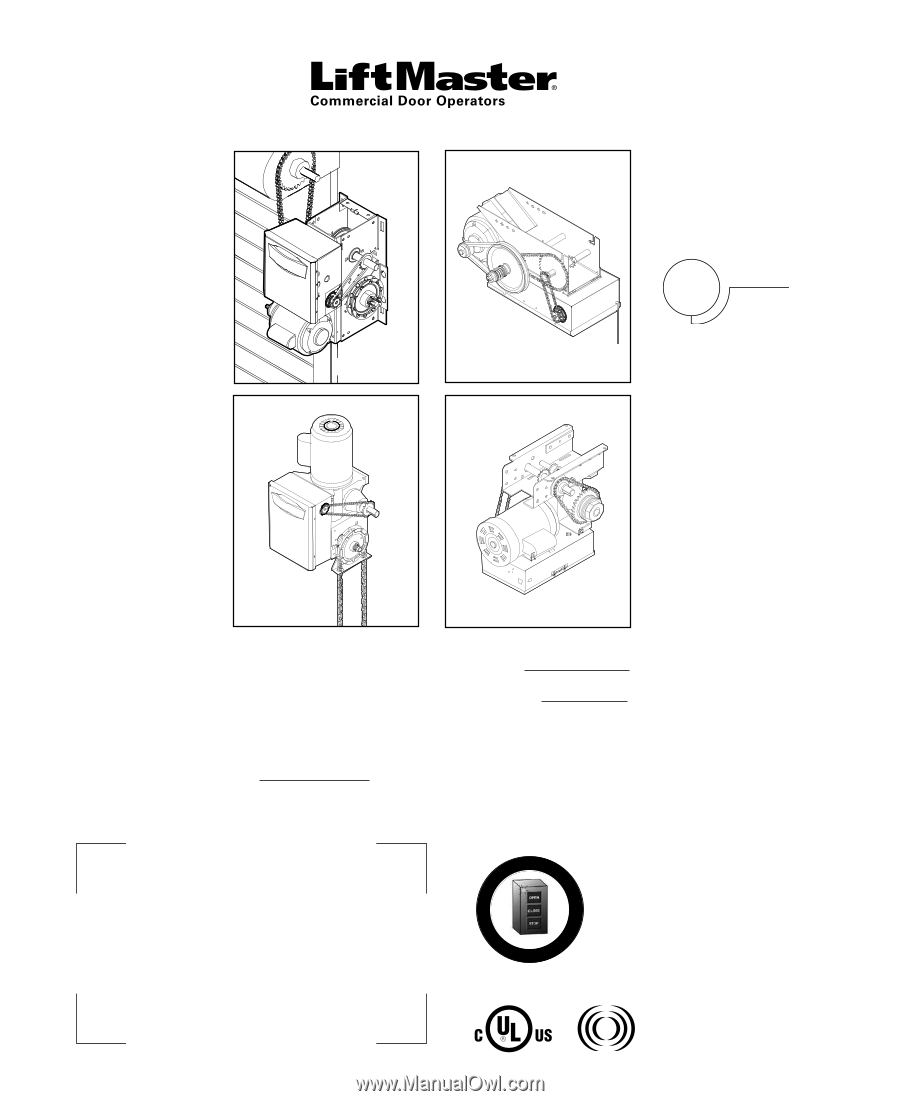
INSTALLATION MANUAL
GT
T AND APT
H, J, AND HJ
GH
A
L
E
R
T
S
Y
S
T
E
M
M
A
I
N
T
E
N
A
N
C
E
PATENT PENDING
The Maintenance Alert System™ allows the installer
to set an internal Maintenance Cycle Counter. The
Logic 4 operator incorporates a self-diagnostic
feature built into the (MAS) Maintenance Alert
System LED. An LED on the 3-button station will
signal when the set number of cycles/months is
reached or when the operator requires immediate
service.
THIS OPERATOR FEATURES THE ENHANCED
Radio Receiver
Built on Board
315MHz
NOT FOR RESIDENTIAL USE
Serial # Box
Installation Date
2 YEAR WARRANTY
THIS PRODUCT IS TO BE
INSTALLED AND SERVICED
BY A TRAINED DOOR
SYSTEMS TECHNICIAN
ONLY.
Operators are shipped in C2
operating mode.
Visit www.liftmaster.com to locate
a professional installing dealer in
your area.
CONTACT INFORMATION