LiftMaster GH GT- Logic 4 Installation Manual - Page 9
Assemble The Operator Model Apt
 |
View all LiftMaster GH manuals
Add to My Manuals
Save this manual to your list of manuals |
Page 9 highlights
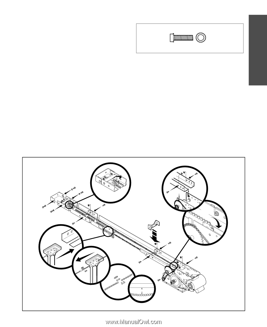
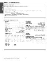
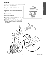
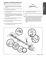
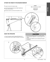
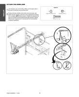
TROLLEY ASSEMBLE THE OPERATOR (MODEL APT) NOTE: If your model is not an APT, proceed to the next page. HARDWARE 1 Install the track spacers evenly over the length of the track. Fasten the spacers to the track with bolt (A) and flange hex nuts (B). 2 Install the front idler in the second set of holes on the end of the track with bolts (A) and nuts (B). A Bolt 3/8"-16 x 3/4" B Flange Hex Nut 3/8"-16 3 8 Slide the trolley onto the track so the door arm hole faces the front (towards the door). Pull the release clip on the trolley and push the end of the chain through the slot in the trolley. 4 Insert bolts (A) into the end of the track and loosely thread the nuts (B) onto the ends of the bolts. Slide bolts (A) on the end of the track assembly into the "L" slot in the operator and tighten nuts (B). 5 Insert bolts (A) into the holes on the end of the track and the operator. Secure the track with nuts (B). 6 Run the chain along the track to the front idler. Wrap the chain around the front idler. 9 Attach one end of the chain to the drive link using a master link. 10 Attach the other end of the chain to the free end of the drive link using a master link and making sure the chain has the correct tension (the chain should sag about 3 inches at the mid point of the track). The chain will need to be cut for proper adjustment. The take-up bolt can be loosened or tightened to adjust the slack of the chain. Slide the trolley back and forth past the drive chain to ensure there is no binding. 7 Run the chain along the track to the operator. Wrap the chain around the operator drive sprocket. 2 6 1 3 8 9 10 3˝ 9 4 7 5 Assembly - Trolley
-
 1
1 -
2
-
3
-
 4
4 -
 5
5 -
 6
6 -
 7
7 -
 8
8 -
 9
9 -
 10
10 -
 11
11 -
 12
12 -
 13
13 -
 14
14 -
15
-
16
-
17
-
18
-
19
-
20
-
21
-
22
-
23
-
24
-
25
-
26
-
27
-
28
-
29
-
30
-
31
-
32
-
33
-
34
-
35
-
36
-
37
-
38
-
39
-
40
-
41
-
42
-
43
-
44
 |
 |