LiftMaster GH GT- Logic 4 Installation Manual - Page 28
Programming
 |
View all LiftMaster GH manuals
Add to My Manuals
Save this manual to your list of manuals |
Page 28 highlights
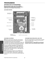
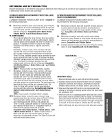
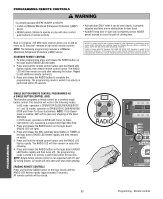
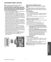
PROGRAMMING INTRODUCTION TO PROGRAMMING Many programmable functions require that a LiftMaster Entrapment Protection (LMEP) device be installed in order to function. Refer to the Entrapment Protection section. LOGIC BOARD OVERVIEW DATA Optional Auxiliary Card Receptacles SLOT 1 SLOT 2 Motor Direction Jumper Maximum Run Timer Button Radio Learn Button Mid Stop Learn Button Timer-To-Close Learn Button REV MOTOR STD DIRECTION OLS MID SLS 3-PHASE 1-PHASE 24VAC POWER 24VAC TIMER DEFEAT COMMON MAS CLS LMEP: MRT MID TTC TIMER ENABLE EDGE: OPEN RADIO 1 2 3 CLOSE T E2 D1 C2 B2 TS FSTS DIAG OPTN PROG STOP COMMON RELAY A RELAY B SBC Single Phase & Three Phase Jumper Maintenance Alert System Button for Programming Open Button Close Button Stop Button Control Wiring Terminal Block Selector Dial (used for programming and selecting wiring type) Main Motor Control Harness Connection LOGIC BOARD LED OVERVIEW NOTE: Before programming the logic board, set the operator's open and close limits. LEDs on the logic board are provided to assist setting the limits. As each limit is activated the corresponding LED will light up. The abbreviations are Open Limit Switch (OLS), Close Limit Switch (CLS) and Sensing Limit Switch (SLS). Refer to page 19 for limit switch adjustment instructions. When power is applied to the operator, the following LED's will illuminate: STOP, CLOSE, OPEN, LMEP, 24Vac, RADIO, DATA, TIMER ENABLE, OLS MID, SLS, CLS, and MAS. Once the power up process is completed (approximately 2-3 seconds) only the appropriate LED's will continue to be lit (i.e., STOP, 24Vdc, limit LED(s) if limit(s) is activated). NOTE: When the power up process is over, the MAS LED will blink a code indicating the version of firmware. If the selector dial is in the DIAG, OPTN, or PROG position, the MAS will not provide this code. After the code has been provided the MAS LED will go out. LOGIC BOARD PUSH BUTTONS (OPEN, CLOSE, STOP) Open, Close and Stop buttons are mounted directly on the logic board. Thus, making it easy to program as well as have door control at the electrical box. Either the stop control or a jumper MUST be wired between terminals 4 and 5 for the on board push buttons to function. PROGRAMMING Programming-Introduction to programming 28
-
 1
1 -
2
-
3
-
4
-
5
-
6
-
7
-
8
-
9
-
10
-
11
-
12
-
13
-
14
-
15
-
16
-
17
-
18
-
19
-
20
-
21
-
22
-
 23
23 -
 24
24 -
 25
25 -
 26
26 -
 27
27 -
 28
28 -
 29
29 -
 30
30 -
 31
31 -
 32
32 -
 33
33 -
34
-
35
-
36
-
37
-
38
-
39
-
40
-
41
-
42
-
43
-
44
 |
 |
