Motorola V186 User Manual
Motorola V186 - Cell Phone - GSM Manual
 |
View all Motorola V186 manuals
Add to My Manuals
Save this manual to your list of manuals |
Motorola V186 manual content summary:
- Motorola V186 | User Manual - Page 1
System Planner ACE3600 RTU 6802979C45-D Draft 2 ab Copyright © 2009 Motorola All Rights Reserved March 2009 - Motorola V186 | User Manual - Page 2
, except for the normal non-exclusive, royalty free license to use that arises by operation in law of the sale of a product. TRADEMARKS MOTOROLA and the Stylized M Logo are registered in the U.S. Patent and Trademark Office. All other product or service names are the property of their respective - Motorola V186 | User Manual - Page 3
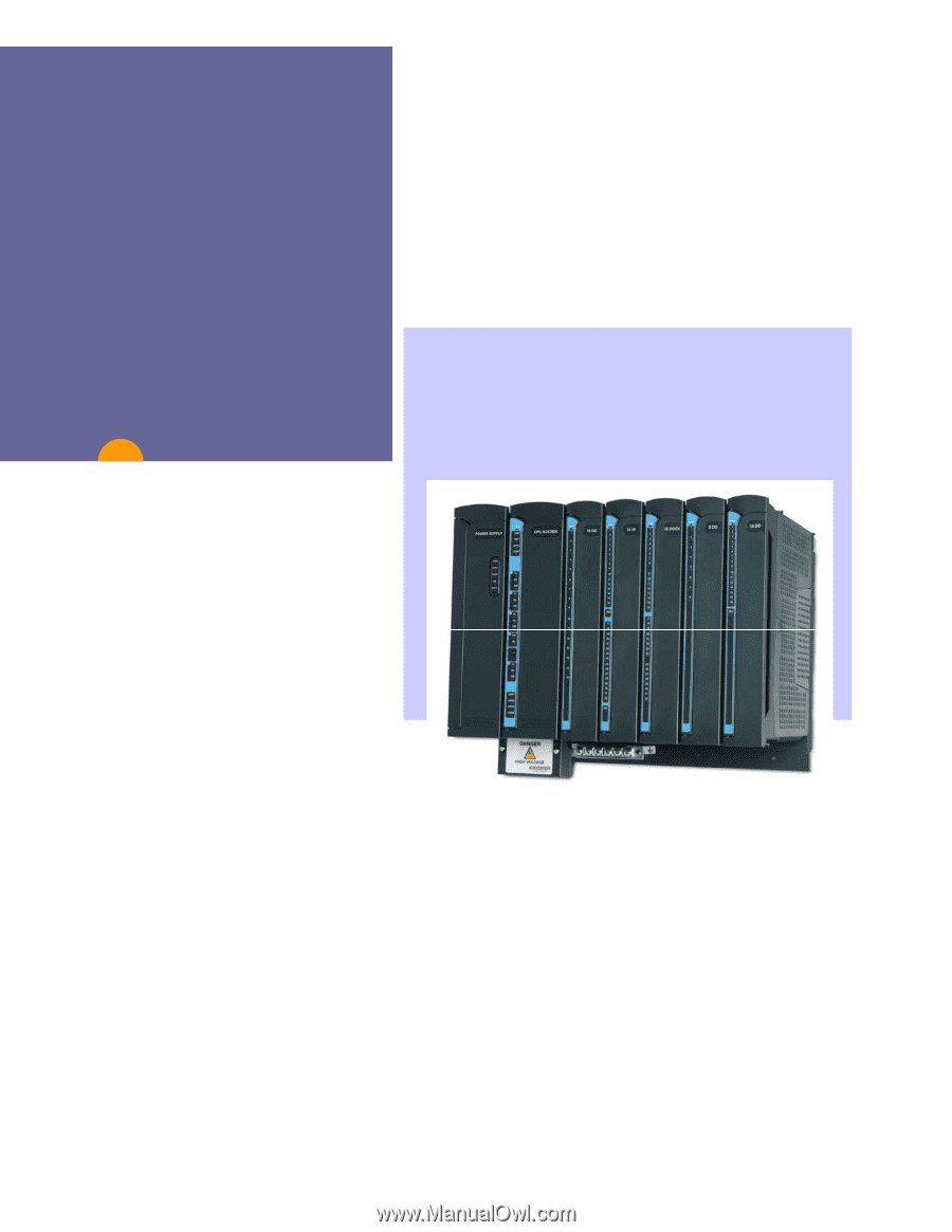
1 ACE3600 RTU CONSTRUCTION 3 POWER SUPPLY MODULES ...6 12V BACKUP BATTERY...7 CPU MODULES...8 I/O MODULES ...10 DIGITAL INPUT MODULES 13 DIGITAL EXPANSION...56 EXPANSION POWER SUPPLY MODULE 60 EXPANSION MODULE...61 MODULE FIRMWARE AND OPERATION MODES 62 EXPANSION LAN SWITCH...65 RTU I/O EXPANSION - Motorola V186 | User Manual - Page 4
167 EXPANSION POWER SUPPLY MODULE SPECIFICATIONS 169 EXPANSION MODULE SPECIFICATIONS 170 EXPANSION LAN SWITCH SPECIFICATIONS 171 APPENDIX B - FCC INFORMATION SPECTRUM AND REGULATORY UPDATE... 172 FCC RULES UPDATE ...172 LICENSING OF FIXED DATA SYSTEMS 175 SPECTRUM AVAILABLE FOR FIXED - Motorola V186 | User Manual - Page 5
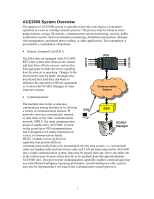
incorporated into the total system, i.e. conventional radio and trunked radio and microwave radio and LAN all interconnected by ACE3600 into a single communication system. Data may be passed from any site to any other site in the system (peer-to-peer) either directly or by multiple hops through - Motorola V186 | User Manual - Page 6
to ACE3600 that are not provided by the SCADA Manager software (over-the-air programming download, diagnostics upload, and more.) • SCADA Manager: The easily supports the desired graphic symbols used on the custom screens. The report capability may be provided by the SCADA software or a data export - Motorola V186 | User Manual - Page 7
may make changes to the local process; messages may be initiated that send data elsewhere to influence the operation of off-site equipment or to advise the SCADA backup battery and communication interfaces ƒ Protective housing which accommodates the frame, and optional radios, backup battery and - Motorola V186 | User Manual - Page 8
or in housing. Power supply and CPU, up to 8 I/Os Can be ordered with metal chassis option for accessories: 6.5 or 10 Ah Lead-Acid backup battery up to 2 radios; up to four plastic boxes. Power supply and CPU, up to 3 I/Os, 1 mobile/portable radio, 1 plastic interface box, 6.5 Ah Lead-Acid backup - Motorola V186 | User Manual - Page 9
and other accessories. Can be installed on a wall or in housing. Small NEMA 4/IP65 housing Enables installation of radio, backup battery and other accessories. Can be installed on a wall. Capacity/Options Power supply and CPU, up to 7 I/Os, 1 plastic interface box, up to 2 mobile/portable radios - Motorola V186 | User Manual - Page 10
ƒ DC power supply (18-72V) with battery charger ƒ AC power supply- 100-240V ƒ AC power supply- 100-240V with battery charger Common characteristics of all power supply modules: ( modules. Note: The DC power supply low-tier does not support radios that require input power other than 10.8-16V. Do not - Motorola V186 | User Manual - Page 11
supply modules with battery charger option charge the backup battery when not in use, and protect the battery from over-discharge. The charger performs battery tests/diagnostics, including controlled battery discharge, when requested by the user. If the battery is failed, the charger will not charge - Motorola V186 | User Manual - Page 12
. The FLASH stores the firmware, the user application program, and the user data. The SDRAM memory stores the temporary data. The optional SRAM memory expansion is used for logging user data. The SRAM data is retained using an on-board rechargeable lithium battery. Model 3610 Model 3640 Flash - Motorola V186 | User Manual - Page 13
from the factory with the most recent firmware version, and it can be updated/replaced using a remote or local connection. Downloading firmware updates is performed using the STS. (See Downloading to a Site in the ACE3600 STS User Guide.) If the new firmware download stops or fails, the CPU will - Motorola V186 | User Manual - Page 14
in the holder. The module and the TB holder provide a coding mechanism to prevent cabling errors. Ejector handles enable easy release of the is available. A TB holder kit is available to enable self-assembly of cables. User assembled cables should use wires of up to 0.4mm (26 AWG) in modules with - Motorola V186 | User Manual - Page 15
Holder I/O Modules I/O Module Ejector Handles Terminal Blocks (TB) Terminal Block (TB) Positioner Screw Terminal Block (TB) Positioner OF 16 UF OF 24V Code Key Code Key TB Holder I/O Module Up to two 24V DC floating plug-in power supplies can be added to certain I/O modules, as detailed in - Motorola V186 | User Manual - Page 16
I/O Modules Spacers Optional 24V Floating ERR 1 UF Power Supply OF 2 UF Plug-In OF 3 UF OF 4 UF OF Motherboard 5 UF OF Location PIN 6 UF OF 7 UF OF 8 UF Motherboard OF 24V Connector 9 UF OF 10 UF OF 11 UF OF 12 UF OF 13 UF OF 14 UF OF 15 UF OF 16 UF OF 24V - Motorola V186 | User Manual - Page 17
(see the specifications below.) All the inputs are optically isolated. The DI modules support optional 24V DC floating plug-in power supplies (for contact "wetting" or other purposes). The 16 DI Fast 24V and 32 DI Fast 24V modules can handle AC and DC input signals. The user - Motorola V186 | User Manual - Page 18
table below. Some parameters are per module and some are per input. Feature DC or AC operation∗ Fast Capture DI Filter (DC) Parameter Settings AC Filter parameter value is 7.0 mSec. Each DI can be set in the user application program's I/O link table to trigger recording of time tagged events upon - Motorola V186 | User Manual - Page 19
possible to set the DI module to Freeze Mode. In this mode the user application program will get the predefined value of each input in the module of the actual input value. Freeze mode enables testing the inputs while the user application program is running. Connection of a dry contact sensor to the - Motorola V186 | User Manual - Page 20
16 DI Module Block Diagram: 16 DI Digital Input Modules 16 - Motorola V186 | User Manual - Page 21
32 DI Module Block Diagram: Digital Input Modules 17 - Motorola V186 | User Manual - Page 22
Low Voltage DI I/O Connection Diagram: Dry Contact Sensor External + Wetting Source - External + Wetting Source - + "Wet" Sensor - Digital Input Modules DI Module DIx (input x) COM (common) DI Module DIx (input x) COM (common) Dry Contact Sensor + "Wet" Sensor - DI Module DIx (input x) +24V ( - Motorola V186 | User Manual - Page 23
Digital Input Modules High Voltage DI I/O Circuit Diagram: DI Status High Voltage DI - Typical Input Circuit 10KΩ 1238Ω DI 47nF COM 62V Current Circuit 19 - Motorola V186 | User Manual - Page 24
16 DI 120/230V Module Block Diagram: 16 DI High Voltage 1 DI1 2 DI2 3 DI3 4 DI4 5 6 7 DI5 8 DI6 9 10 COM 1-6 Input Circuit 11 DI7 12 DI8 13 DI9 14 DI10 15 16 17 DI11 18 DI12 19 20 COM 7-12 21 DI13 22 DI14 23 DI15 24 DI16 25 26 27 28 29 30 Digital Input Modules Control Bus Interface 20 - Motorola V186 | User Manual - Page 25
16 DI 120/230V I/O Connection Diagram: AC / DC Signal Source Digital Input Modules DI 120/230V Module DIx (input x) COM (Common) AC / DC Signal Source Ext. Relay / Switch DI 120/230V Module DIx (input x) COM (Common) 21 - Motorola V186 | User Manual - Page 26
Digital Output Relay Modules Low Voltage DO Relay Modules: The DO Relay modules have 8 or 16 outputs. There are two types of DO relays: ƒ Electrically Energized (EE) - the outputs return to the non-energized state in case of power off or module failure. ƒ Magnetic Latch (ML) - Relay outputs are - Motorola V186 | User Manual - Page 27
to a "Predefined Value" (PDV 0 or 1). This value is executed when the user program stops or when the module has no communication with the CPU module. Also, the during normal operation to force a value on the output by ignoring the user program value (mask). In the ML relay modules, it is possible to - Motorola V186 | User Manual - Page 28
time they were frozen. Freeze mode enables testing the inputs and outputs while the user program is running. Note: In systems with I/O expansion, the power supplies on that were configured by dip switch for 12V DO. This enables the user to inhibit all DO EE relays in the entire RTU simply by removing - Motorola V186 | User Manual - Page 29
Digital Output Relay Modules Low Voltage I/O Circuit Diagrams: DO EE Relay (SPST) - Typical Output Circuit 12V Back Indication DO Control COM NO DO ML Relay (SPST) - Typical Output Circuit 12V Back Indication DO Set Control DO Reset Control COM NO 25 - Motorola V186 | User Manual - Page 30
Digital Output Relay Modules DO EE Relay (SPDT) - Typical Output Circuit 12V Back Indication DO Control NC COM NO DO ML Relay (SPDT) - Typical Output Circuit 12V Back Indication DO Set Control NC COM NO DO Reset Control 26 - Motorola V186 | User Manual - Page 31
8 DO Module Block Diagram Digital Output Relay Modules 27 - Motorola V186 | User Manual - Page 32
16 DO Module Block Diagram: Digital Output Relay Modules 28 - Motorola V186 | User Manual - Page 33
Digital Output Relay Modules 120/230V DO I/O Circuit Diagram: HV DO EE Relay (SPST) - Typical Output Circuit 12V Back Indication NO DO Control HV DO ML Relay (SPST) - Typical Output Circuit 12V Back Indication NO DO Set Control DO Reset Control 29 - Motorola V186 | User Manual - Page 34
Digital Output Relay Modules 120/230V DO Module Block Diagram: Vr 12 V 12 V DO (User Controlled) 1 2 NO1 3 4 NO2 5 6 7 8 NO3 9 10 NO4 Back Indication Vr V 11 12 NO5 13 14 NO6 15 16 17 18 NO7 19 20 NO8 Module Control - Motorola V186 | User Manual - Page 35
data to the CPU module. The following modules are available: ƒ 8 AI, ±20 mA (supports 4-20 mA) ƒ 16 AI, ±20 mA (supports 4-20 mA) ƒ 8 AI, ±5 V (supports 0-5 V and 1-5 V) ƒ 16 AI, ±5 V (supports filtered to reduce 50 or 60 Hz noise. The user can select the filtering frequency per module. The measured - Motorola V186 | User Manual - Page 36
V and 1-5 V. ƒ "Keep Last Value" (KLV) and "Predefined Value" (PDV) - Each input can be configured to KLV or to a PDV. This value is shown to the user application program in the event of AI module failure. The predefined value can also be used during normal operation to force a value that masks the - Motorola V186 | User Manual - Page 37
the CPU in the Error Logger. AI Module failure status is also visible to the user application program. In addition to the ERR LED, the module includes an Underflow (UDF) to set the AI module to Freeze Mode. In this mode, the program user will get the KLV or PDV of each input in the module instead of - Motorola V186 | User Manual - Page 38
Analog Input Modules AI Module Value Representation: In ± 20 mA current inputs Decimal Value < -32256 -32000 0 32000 > 32256 Input Current < -20.16 mA -20 mA 0 mA +20 mA > +20.16 mA Indication Underflow LED ON Rated range (no LED active) Overflow LED ON In 4 - 20 mA current inputs Decimal - Motorola V186 | User Manual - Page 39
Analog Input Modules I/O Circuit Diagram: AI ±20 mA - Typical Input Circuit AN+ A/D Channel Select 124Ω 15V 51Ω PGND AN - AI ±10 V - Typical Input Circuit 51Ω AN+ A/D Channel Select 15V 51Ω PGND AN - 35 - Motorola V186 | User Manual - Page 40
8 AI Module Block Diagram: Analog Input Modules 36 - Motorola V186 | User Manual - Page 41
16 AI Module Block Diagram: Analog Input Modules 37 - Motorola V186 | User Manual - Page 42
Analog Input Modules I/O Connection Diagrams: There are two types of current sensors/transmitters, namely 2-wire and 4-wire. The 2wire transmitters require a serial power feed for the current loop, whereas 4-wire transmitters have a separate power supply connection. As a result, with 4-wire - Motorola V186 | User Manual - Page 43
includes: ƒ AO Type - The analog outputs can be set to voltage, current, or raw data. ƒ AO Value - The analog outputs can be set to a numeric value (in the value. ƒ Sleep Mode - Each AO module can be switched by the user application program to Sleep Mode. In Sleep Mode, the module does not function and - Motorola V186 | User Manual - Page 44
. On On Off Vout is uncalibrated. Off On On Both outputs are defined by the user, either using HW test or user application program to send raw data. Off On Off Vout is defined by the user, either using HW test or user application program. Off Off On Iout is defined by the - Motorola V186 | User Manual - Page 45
, the AOs will keep the last value they had at the time they were frozen. Freeze mode enables testing the inputs and outputs while the user program is running. AO Module Value Representation: In 0-20 mA current outputs In 0- 10 V voltage outputs Decimal Value 0 4000 8000 16000 Decimal Value 0 4000 - Motorola V186 | User Manual - Page 46
Analog Output Modules I/O Circuit Diagram: AO - Typical Output Circuit Variable 12V Current source 50Ω 330Ω 20V Floating Voltage Converter 30 V D/A Control - + Variable Voltage source 30 V 26V Iout PGND RET Vout 42 - Motorola V186 | User Manual - Page 47
4 AO Module Block Diagram: Analog Output Modules 43 - Motorola V186 | User Manual - Page 48
I/O Connection Diagram: Current Output wiri ng + Device / Load - S hie ld Analog Output Modules AO Module Iout x Ret x Volta ge O utput wiri ng + Device / Load - S hie ld AI Mo dule Vout x Ret x 44 - Motorola V186 | User Manual - Page 49
Digital Output and Digital Input FET Modules The Digital Output/Digital Input (DO/DI) FET modules have 16 or 32 configurable user connections, organized in groups. Each group can be configured as an 8 DO group or as an 8 DI group. The outputs are optically isolated current sink - Motorola V186 | User Manual - Page 50
module. Also, the predefined value can be used during normal operation to force a value on the output by ignoring the user application program value. The DO/DI FET module features which can be configured are listed in the table below. Some parameters are per module and some are per input. Parameter - Motorola V186 | User Manual - Page 51
the Error Logger. DO/DI module failure status is also visible to the user application program. The DO/DI module can be diagnosed and monitored using the is possible to set the module to Freeze Mode. In this mode the user application program will get the KLV/PDV of each input in the module instead - Motorola V186 | User Manual - Page 52
Digital Output and Digital Input FET Modules I/O Circuit Diagram: DO/DI - Typical I/O Circuit 12V 5V Floating Voltage Converter DI Status/ 20KΩ Self Recovery Fuse 1A DO Back Indication * 33V DO Control * FET Always "OFF" in DI configuration DO/DI COM 48 - Motorola V186 | User Manual - Page 53
Digital Output and Digital Input FET Modules 16 DO/DI Module Block Diagram: 49 - Motorola V186 | User Manual - Page 54
Digital Output and Digital Input FET Modules 32 DO/DI Module Block Diagram: 50 - Motorola V186 | User Manual - Page 55
I/O Connection Diagram: DI wiring Dry Contacts Switch / Sensor Digital Output and Digital Input FET Modules DO/DI FET Module DIx (input x) COM (Common) DO wiring DC + Source - Load DO/DI FET Module Diode (Inductive load) DOx (Output x) COM (Common) 51 - Motorola V186 | User Manual - Page 56
Mixed I/O Modules The ACE3600 Mixed I/O modules include a mixture of Digital Inputs, Relay Outputs and Analog Inputs on the same module. The available Mixed I/O modules are: ƒ 16 Digital Inputs + 4 EE DO Relay Outputs + 4 Analog Inputs ( ±20 mA) ƒ 16 Digital Inputs + 4 ML DO Relay Outputs + 4 Analog - Motorola V186 | User Manual - Page 57
Mixed I/O Module Block Diagram: Mixed I/O Modules 53 - Motorola V186 | User Manual - Page 58
the Analog Input Modules chapter. For a description of the AOs in the Mixed Analog modules, see the Analog Output Modules chapter. The Mixed Analog modules support an optional 24V DC floating plug-in power supply to power external devices. 54 - Motorola V186 | User Manual - Page 59
Mixed Analog Module Block Diagram: Mixed Analog Modules 55 - Motorola V186 | User Manual - Page 60
expansion is based on a 100 Base-T full duplex Ethernet connection between the CPU module and the expansion modules. This type of connection enables the user program application to control and monitor the I/O modules on the expansion frames transparently as if they are located on the main frame. The - Motorola V186 | User Manual - Page 61
supply on the I/O expansion frame is attached via DC cable to the power supply on the main frame. Accessories such as a mobile radio, battery, etc. are attached to a separate optional 19" chassis. Main Rack Radio/Batt. Chassis (optional) Main PS (AC/DC) CPU (3640) Expansion Switch Communication - Motorola V186 | User Manual - Page 62
I/O Expansion Note: The number of expansion power supplies that can be cascaded to the power supply on the main frame is limited. When required, optional DC or AC power supplies should be installed on the expansion frames to meet the accumulated power consumption and voltage level requirements. In - Motorola V186 | User Manual - Page 63
of power supplies for a system with I/O expansion is determined by the specific configuration and the power requirements of the system. In a co-located system the expansion module to restart, see the ACE3600 STS User Guide - Appendix A: Site Configuration Parameters. Status and Diagnostics Status - Motorola V186 | User Manual - Page 64
cable to the power supply on the previous I/O expansion frame in a daisy-chain manner, the main power supply controls the entire RTU. This enables the user to turn off the entire RTU simply by turning off the main power supply. If the main power supply does not control all other power - Motorola V186 | User Manual - Page 65
to control the I/O modules on the expansion frame and process the gathered data. This module is installed in the I/O expansion frame in the CPU slot . The expansion module includes a (rotary) selector switch which enables the user to determine the frame number in the expanded RTU. The frame number - Motorola V186 | User Manual - Page 66
or connection of the first LAN switch to the second, if such exists. ƒ 2 meter (Motorola p/n V648 / FKN8562A) ƒ 3 meter (Motorola p/n V666 / FKN8563A) Module Firmware and Operation Modes The expansion module firmware extends the main CPU control to the I/O modules located in the expansion frame. The - Motorola V186 | User Manual - Page 67
Image into RAM from the MCPU (using TCP). 2. Turns off all LEDs and runs the loaded Expansion Firmware Image. 3. Auto-recognizes actual I/O modules. Loads user files from the MCPU (using TCP) and saves in FLASH: 1. Configuration, if such exists 2. Application database, if such exists 3. Predefined - Motorola V186 | User Manual - Page 68
The expansion module constantly exchanges I/O data and status data with the main CPU, using the Ethernet Micro-code Interface (EMI). The EMI enables the , it is possible to download to the RTU a user program or other user defined files. After successful download, the main CPU automatically - Motorola V186 | User Manual - Page 69
ACE3600 expansion LAN switch is configured to prioritize different Ethernet data frame types. A special protocol, used for communication between the utility. The expansion LAN switch option includes a 60 cm Ethernet cable (Motorola p/n V529/FKN8561A). Use this cable to connect from the Eth1 port on - Motorola V186 | User Manual - Page 70
connected to expansion LAN switch 2 ports Eth2-Eth8 respectively.) If the expansion frames are not physically connected as described above, the switch connection must be manually configured in the STS Switch Connections dialog. For more information, see the ACE3600 STS - Motorola V186 | User Manual - Page 71
is described in the ACE3600 Owner's Manual and in this document in Appendix C: ACE3600 Maximum Power Ratings. The accumulated power consumption from the main power supply (located in the main frame) should not exceed its maximum current output specifications. Consider the following example: ƒ An - Motorola V186 | User Manual - Page 72
I/O Expansion Each cascaded expansion power supply gets a lower input voltage from the preceding power supply. The voltage drop is a function of the expansion power cable resistance and the current flowing through the cable (which is the accumulated current of the expansion frame and all the - Motorola V186 | User Manual - Page 73
Vo depends on the power supply configuration. Vo should be 13 V DC when the backup battery option is not used. If the battery option is used with the main power supply, during power fail Vo depends on the battery voltage (which may be below 13 V DC). It is highly recommended to use at - Motorola V186 | User Manual - Page 74
Ordering Information ACE3600 RTU Ordering Flow: For RTUs without I/O expansions, follow only the ordering steps for Main Frame below. Main Frame - Step 1 Select ACE3600 model Note: CE countries (Western Europe) can only order ACE without radio (F7509) Model F7509 Without Radio Model Type? With - Motorola V186 | User Manual - Page 75
Ordering Information ! The default frame includes CPU3610 and 12V DC PS 8 I/O Slots fits wall mount and 19" rack only The number of modules MUST match the number of available I/O slots Expansion LAN Switch occupies I/O module slot Cables Main Frame - Step 2 Set # of I/O Modules Slots and add I/O - Motorola V186 | User Manual - Page 76
Ordering Information Main Frame - Step 3 Select installation type ! For models with radio and/or battery you must add metal chassis or housing 0 or 3 Add small / large metal chassis OR small / large housing option Need chassis, No housing or 19" installation? - Motorola V186 | User Manual - Page 77
Information ! Default PS is 12 V DC Main Frame - Step 4 Select PS & Battery Change No Default PS Yes Yes Needs No backup battery? Add AC PS or DC PS with charger option Add AC PS or DC PS without charger option Large chassis /housing What type of Installation? Small chassis /housing - Motorola V186 | User Manual - Page 78
Ordering Information ! Default CPU is CPU3610 I/O Expansion Requires CPU3640 Main Frame - Step 5 Select CPU and Plug-in Change No Default CPU Yes Add CPU3640 option Please note! Conventional Radio Installation Kit includes radio modem plug-in No Need Plug-in option Yes Add CPU Plug-in - Motorola V186 | User Manual - Page 79
Ordering Information Main Frame - Step 6 Miscellaneous Tamper switch, RS485 Junction Box, dummy module, etc. Need No miscellaneous Options? Yes Add miscellaneous Options Need I/O Expansion? No End Yes Go to Expansion Frame - Step 1 75 - Motorola V186 | User Manual - Page 80
! The default frame includes Expansion module and Expansion PS 8 I/O Slots fits wall mount and 19" rack only The number of modules MUST match the number of available I/O slots Cables Ordering Information Expansion Frame - Step 1 Select model Set # of I/O Modules Slots and add I/O modules Select - Motorola V186 | User Manual - Page 81
Ordering Information Expansion Frame - Step 2 Select installation type ! For models with battery you must add metal chassis or housing 0 or 3 Add small / large metal chassis OR small / large housing option Need chassis, No housing or 19" installation? - Motorola V186 | User Manual - Page 82
if the expansion is not located with the main frame Yes Change No Default PS Yes Needs No backup battery? Add AC PS or DC PS with charger option Add AC PS or DC PS without charger option Large chassis /housing What type of Installation? Small chassis /housing Add 6.5 Ah or 10 Ah - Motorola V186 | User Manual - Page 83
Ordering Information Expansion Frame - Step 4 Miscellaneous Tamper switch, LAN cable, Dummy module, Driver license, etc. Need No miscellaneous Options? Yes Add miscellaneous Options Need Yes additional I/O Expansion? No End Go to Expansion Frame - Step 1 79 - Motorola V186 | User Manual - Page 84
MHz Digital Trunked 800MHz Radio Models • ACE3600 with XTL2500 800MHz Analog • ACE3600 with XTL2500 800MHz Digital • ACE3600 with XTS2500 800MHz Digital Software • ACE3600 System Tool Suite (STS) • ACE3600 C Toolkit (CTK) • ACE3600 Enhanced PID F7509 F7510 F7573 F7563 F7553 F7574 F7564 F7554 F7533 - Motorola V186 | User Manual - Page 85
Ordering Information Note: All radio models require Metal Chassis or Housing option. IMPORTANT: Only model F7509A and all its options, including radio installation kits, may be shipped to European Union (EU) countries. The installer must confirm that there are no emissions or harmful interference to - Motorola V186 | User Manual - Page 86
Power Supply Low-Tier 10.8-16V • AC Power Supply 100-240 V • DC Power Supply 18-72V • AC PS 100-240 V with Battery charger • DC PS 18-72V with Battery charger • 6.5 Ah Backup Battery 82 Ordering Information V851 V852 V853 V854 V951 V952 V953 V954 V103 V105 V107 V108 V051 V056 V214 V269 V228 VA00405 - Motorola V186 | User Manual - Page 87
• 10 Ah Backup Battery CPU Upgrade (Default CPU is CPU3610) • ACE CPU3640 • Plug-in SRAM CPU Plug-in Ports • Plug-in RS232 Port • Plug-in RS 485 PORT • Plug- - Motorola V186 | User Manual - Page 88
Interface RS485 Connection Box Third Party Protocol Third party protocol license Accessories • ACT module • 24V Plug-in Floating Power Supply Software License (RTU Options) • AGA 7+8 License • DNP3+ License • IEC 60870-5-101 License Ordering Information V20 V253 V202 V358 V158 V203 V153 - Motorola V186 | User Manual - Page 89
radio or analog trunked radio are provided with plug-in radio modem installed in the CPU module. 10. Models with radio and orders that include battery option or accessories option (such as RS-485 Junction Box) must be ordered with metal chassis or housing options (mandatory). 11. Model F7510 - Motorola V186 | User Manual - Page 90
on a 19" rack. Note: For specific installation instructions, please refer to the ACE3600 Owner's manual. Dimensions Frame Dimensions: • No I/O Large - for PS, CPU and up to 7 I/O slot frame, two radios and 6.5 or 10 Ah backup battery, wall mount , 448 x 468 mm x 200 D** mm (17.64"x 18.43" x 7.88") - Motorola V186 | User Manual - Page 91
Guidelines GENERAL SAFETY INFORMATION: WARNING: Installation of the ACE3600 should be done only by authorized and qualified service personnel in accordance with the US National Electrical Code. Only UL Listed parts and components will be used for installation. Use UL Listed devices having an - Motorola V186 | User Manual - Page 92
ACE3600 Installation Guidelines Mounting the ACE3600 Frame on a Wall WARNING: Before drilling holes for mounting the frame, make sure there are no electrical wires installed inside the wall at the holes' location. CAUTION: If the ACE3600 is subject to high levels of shock or vibration, you must - Motorola V186 | User Manual - Page 93
117 mm 82 mm ACE3600 Installation Guidelines 234 mm 199.6 mm 209 mm 124 mm 244 mm 124 mm 0 I/O Frame 3 I/O Frame No I/O and 3 I/O Frame Installation Dimensions and Screw Holes for Installation 314 mm 278.5 mm 391 mm 356.9 mm 244 mm 124 mm 244 mm 124 mm 5 I/O Frame 7 I/O Large Frame 5 I/O - Motorola V186 | User Manual - Page 94
ACE3600 Installation Guidelines Installing the ACE3600 in a 19" Rack The 8 I/O slot frame and the 8 I/O (19") Metal Chassis (V269) can be installed on 19" racks using the 19" rack brackets for 8 I/O slots frame (V051) as depicted in the pictures below. 90 - Motorola V186 | User Manual - Page 95
ACE3600 Installation Guidelines Housing Installation For convenient installation of the ACE3600 RTU with the NEMA 4 housing, allow an additional 6 cm (2.4") (in W, H) and 7 cm (2.75") (in D) around the housing. Four mounting brackets are provided, one in each corner of the RTU, for wall mounting - Motorola V186 | User Manual - Page 96
ACE3600 Installation Guidelines MOUNTING BRACKET PRE±INSTALLED (WELDED) ON SOME HOUSING BRANDS Mounting the NEMA 4 Housing 92 - Motorola V186 | User Manual - Page 97
Service Telephone Network (PSTN) voice/data via dial-up modems, cellular packet data modems and Local Area Networks (LAN). Multiple data user, except in those cases where the communication is to be defined by the user model adapted for SCADA. It supports multiple logical channels per physical port, - Motorola V186 | User Manual - Page 98
MDLC Protocol The MDLC protocol is a Motorola SCADA protocol that is based on the data in variable-length frames and attaches addresses, frame sequence numbers, and Cyclic Redundancy Code (CRC applications such as data transfer, configuration downloading, application software monitoring, remote - Motorola V186 | User Manual - Page 99
to message size in byte notation because of the 16-bit architecture; the data may not be sent in asynchronous format-no start and stop bits-but it (s). The concatenated data words may be any combination of the supported functions, i.e. data upload to the SCADA Manager, error logger data to the STS - Motorola V186 | User Manual - Page 100
stack are commonly known as Network Services. These layers only are used when communicating with intermediary sites which make it possible to pass any data through the system and not require the total system to know the details of the data. Each layer adds (removes) data to what was received and - Motorola V186 | User Manual - Page 101
the SCADA Manager database at specified intervals or when manually instructed by the operator. The Report-byException method has the RTU report only the conditions/values that have changed since the last poll. The SCADA Manager retains all data conditions and values in a local database for instant - Motorola V186 | User Manual - Page 102
nearly unlimited number of links. The RTU supports a variety of communication media, protocols and data speeds, as detailed below: • Serial RS232 ports, up to 115.2 kbps, supports: - Local PC using MDLC (MDLC or User Protocol) - RTU to RTU (MDLC) - External Data (MAS) radio (MDLC, ModBus RTU, DF1 or - Motorola V186 | User Manual - Page 103
devices in the site to the RTU using the ModBus protocol or a user defined protocol. The RS485 Connection Box is available to make this interconnection; The RS485 port may operate at data speeds up to 460 kbps (depending on the total wire length). The RS485 specification calls for the circuitry to be - Motorola V186 | User Manual - Page 104
cable with its characteristic impedance reduces reflections and increases the achievable data rate. Although normally required at higher transmission frequencies, it is as this can overload the driver and reduce the reliability of the data transfer. The distance can be increased by the use of - Motorola V186 | User Manual - Page 105
of the protocol support IP. MDLC user in a static LAN and the user does not RTU port connected to a packet data radio/modem over PPP (Point to SCADA control center (over PLC or user port). 2. ACE3600 RTU port connected 'C' Toolkit socket (user protocol over IP) data modem/radio over PPP. - Motorola V186 | User Manual - Page 106
10 Mbps half-duplex. Broadcast and Setcalls Most wireless packet data networks do no support broadcast IP. When transmitting a group call (Site 0), IP Gateway. These features apply to Ethernet static IP address, Ethernet DHCP, and RS232 PPP port types. Multiple IP Ports The user can specify more - Motorola V186 | User Manual - Page 107
, such as dynamic addresses of RTUs, there is no need to download that table to FEP, simply because RTUs addresses are updated when they transmit user and network to make sure this is supported. In the IP conversion table, it is possible to set a host name instead of a numeric IP address for a specific - Motorola V186 | User Manual - Page 108
will retrieve its time from a set of NTP servers specified by the user. The clock offset between the RTU and these servers depends on network delays on the 'C' Toolkit socket functions, see the ACE3600 RTU 'C' Toolkit User Guide. Dynamic IP Address Many wireless networks do not allocate a fixed IP - Motorola V186 | User Manual - Page 109
data radio/modem over PPP and have its own link ID. Several RS232 over PPP connections are supported downloaded to a specific port configured for MDLC over IP. The modem/radio can also be diagnosed using AT commands specified in that file. For MDLC over IP this feature since the firmware already has - Motorola V186 | User Manual - Page 110
must be defined. In DHCP address mode, the user is only required to set the link ID for to date. This is called FQDN and is not always supported by the DHCP server (in this case a warning (This feature is the same as in Toolbox V9.54 and MOSCAD V9.25.) Paging a site before transmitting MDLC data to - Motorola V186 | User Manual - Page 111
Communications MDLC over LAN/Ethernet The ACE3600 RTU can communicate over Ethernet media, via the onboard Ethernet port or 10/100BT plug-in ports. The figure below illustrates an example of a SCADA system with IP Gateway and ACE3600 RTUs connected to Ethernet LAN: SCADA Central STS LINE 1 RS- - Motorola V186 | User Manual - Page 112
instructions for configuring an RTU in the Operation chapter in the ACE3600 STS User Guide. must support integrated voice and data (named IV&D). This is relevant to Motorola subscriber data radios radio via an RS232 data cable. Note that a specific codeplug which supports the data option must be used - Motorola V186 | User Manual - Page 113
the radio as it is configured using the CPS (Codeplug Programming Software). STS SCADA Central Ethernet LINE 1 IP RS-232 Gateway Customer an ASTRO IV&D radio, the radio must be context activated, or registered for data, in addition to the PPP connection over RS232 interface. The RTU uses SNMP - Motorola V186 | User Manual - Page 114
For a mobile radio such as the XTL5000, the interface is comprised of a radio data cable over RS232. Note: A PC needs a tool called Data Link Manager (DLM) in order to communicate over the air NOTE: ASTRO IV&D does not support group calls (RTU-to-RTU broadcasts). To send a frame to a group of sites - Motorola V186 | User Manual - Page 115
RTU-B MDLC over Tetra ACE3600 RTUs can be connected to a Tetra radio. Tetra infrastructure and radio should support packet data. The connection to Tetra can be made via LAN or via radio. An IP Gateway or an RTU with and Ethernet plug-in or on- - Motorola V186 | User Manual - Page 116
Tetra PD installation (as specified in the CPS user manual). After setting up the connection, the user should run the STS Communication Setup utility, select reliable. For details, see MDLC over IP Site Paging. Tetra does not support group calls (RTU-to-RTU broadcasts). To send a frame to a group - Motorola V186 | User Manual - Page 117
downloaded. The same concept is used for circuit data modem over dial port. For information of downloading modem configuration files, refer to ACE3600 STS Advanced Features Manual address. Other modems such as Motorola g18 do not have an drops, PPP is disconnected. The user can opt to ignore CD using - Motorola V186 | User Manual - Page 118
modem GPRS infrastructure LINE 1 STS RS-232 g18 GPRS Packet Data modem RTU-A g18 GPRS Packet Data modem RTU-B A single GPRS modem can be connected to an RTU. Other ports can be connected to other GSM modems using dialup ports. It is recommended that the operator provides an APN (Access Point - Motorola V186 | User Manual - Page 119
its APN according to your operator instructions. The APN (Access Point Name) is an address such as intranet.motorola.com. The APN defines the security and capabilities set by your provider for your SIM cards. Note: Each SIM Card has unique identifiers for a GPRS/GSM modem. Placing a given SIM card - Motorola V186 | User Manual - Page 120
, there is no default, and any IP conversion tables must be created manually. The IP conversion table maps sites in the system (site ID+link . FEP 100 LINE 2 Control Center LINE 1 CEN LAN FEP 10.5.1.xx Packet Data Network 192.5.1.xx LAN 155.9.1.xx LINE 2 Subscriber Radio 1 LINE 1 PPP/RS - Motorola V186 | User Manual - Page 121
Make sure the DNS Servers are either learned (DHCP or PPP) or set them manually in port configuration (Static LAN). In this example assume the operator has assigned com FEP2.moto.com In this example, LINE2 is Static LAN so the user needs to set the DNS servers of LINE2 network in the LINE2 port - Motorola V186 | User Manual - Page 122
data ports (configurable, by default 57001, and 57002) • Expansion UDP discovery port (57001, not user configurable) • Timer event (UDP 57003) The firewall also enables the user frames to a main frame with enabled firewall, either: • Manually enter the IP addresses of the expansion frames and main - Motorola V186 | User Manual - Page 123
in many cases the same modem can work in both modes, but the user must decide when configuring the port, what method to use. With MDLC over Dialup, the modem is placed in circuit data mode, meaning it establishes phone call conversations with remote sites upon transmitting to them. It accepts calls - Motorola V186 | User Manual - Page 124
radios can be interfaced to the ACE3600 using the radio modem ports using DPSK 1.2 kbps modulation (for more information consult Motorola support). Radio HT750 - North America GP320 - Europe, Middle East, Africa GP328 - Asia & Pacific Pro5150 - South America CDM750 - North America CM200 - North - Motorola V186 | User Manual - Page 125
Communications Radio FCC information Radio Band Power Output* HT750 VHF 136-174 MHz 1-5W UHF 403-470 MHz 1-4W UHF 450-512 MHz 1-4W CDM750 VHF 136-174 MHz 1-25W UHF 403-470 MHz 1-25W UHF 450-512 MHz 1-25W Transmitter Type Acceptance AZ489FT3794 AZ489FT4826 AZ489FT4834 AZ492FT3796 - Motorola V186 | User Manual - Page 126
the FM transceiver's oscillator. Motorola refers to this modulation technique as users from being heard; it offered the illusion of a private channel. PL/DPL adds a decoder to the receiver that keeps the receiver muted until a signal having a specific low-frequency tone (PL) or slow data code - Motorola V186 | User Manual - Page 127
. The MT-2000 and MCS-2000 radios used within MOSCAD may operate on either 25 kHz or 12.5 kHz bandwidth channels; Radio Service Software is used to define the mode of operation. Radios used for data must meet a minimum efficiency requirement. In a separate action, the FCC clarified key definitions - Motorola V186 | User Manual - Page 128
be used because it is not an F2 emission. PL/DPL must never be used because their deviation (750 Hz) must be subtracted from the data deviation which worsens an already marginal situation. Therefore, DPSK modulation at 1.6 kHz is the only legal emission available for "2800" splinter frequency use - Motorola V186 | User Manual - Page 129
voice radios in the system. This setup may not be optimal for data users. ACE3600 operates best in the Message Trunking mode whereas many systems are revote. System engineers are encouraged to contact the ACE3600 Product Support Group during the design phase of any trunked radio system so that - Motorola V186 | User Manual - Page 130
uses the packet data capability of the Features Manual. Conventional Radio Interoperability Introduction Since the first MOSCAD RTU was introduced to the market, various models of Motorola conventional radios had been used with Motorola of radio, there is a specific delay between the activation of - Motorola V186 | User Manual - Page 131
by the RTUs/FEP radios and the repeater's performance. For technical support concerning setting parameters in system with F1-F2 repeaters, please contact Motorola technical support. Parameter Setting for Motorola Conventional Radios in MOSCAD / ACE3600 Systems Radio Modulation First WarmUp - Motorola V186 | User Manual - Page 132
Communications Setting the Parameters in the MOSCAD/MOSCAD-L ToolBox The Channel Monitor Resolution and First Warm-up Delay parameters are set in the Site configuration -> Port 3 -> Advanced Physical Layer screen. Setting the Parameters in the ACE3600 STS The Channel Monitor Resolution and First - Motorola V186 | User Manual - Page 133
a complex hierarchical system structure, it does not make it complicated. This is because most of the communication interactions are transparent to the user, except in those cases where the communication is to be defined by the ladder application. In such cases, you should perform simple programming - Motorola V186 | User Manual - Page 134
checks, etc. The MDLC protocol is discussed later in this manual. The ACE3600 System Tools Suite (STS) may perform monitoring defined by the system engineer, according to user requirements. Each RTU executes its application and, simultaneously, supports the communications link (or links) defined for - Motorola V186 | User Manual - Page 135
Communications Network Configurations The ACE3600 system supports both simple and complex communication networks. The following sections describe various configurations from different aspects. Simple System A simple system, comprised of a central computer and RTUs - Motorola V186 | User Manual - Page 136
Communications The FEP in the system illustrated above serves as a network node between link RADIO 1 and link LINE 1. Configuring the FEP to have access to two different links enables it to serve as a node between these links. The MDLC protocol permits RTU-to-RTU communications without the - Motorola V186 | User Manual - Page 137
9) is configured as a Store & Forward repeater. It performs data exchange between units that operate on the same frequency but are 9 is a network node between the RADIO 1/1 and RADIO 1/2 links. The network software treats the Store & Forward node as it treats the node between line and radio: - Motorola V186 | User Manual - Page 138
Communications The schematic representation of this system is shown below. The system assumes that the two nodes, RTU 15 and RTU 40, cannot "hear" each other. They communicate via the FEP, which is also a Store & Forward node. This system, therefore, consists of four zones and three nodes (RTU 15, - Motorola V186 | User Manual - Page 139
RTUs in a system at the same time. Encryption is possible on all the types of communication links that use MDLC protocol. MDLC data encryption is supported by: • ACE3600 • MOSCAD IP Gateway • MOSCAD (CPU420) • MOSCAD-L (CPU020) Only encrypted RTUs / IP Gateways that are using the same Encryption Key - Motorola V186 | User Manual - Page 140
Communications 136 - Motorola V186 | User Manual - Page 141
same KF is used by the IP Gateway, the RTUs and the ToolBox MDLC driver. The KF is encrypted and cannot be obtained from without password The KF in . It has the following major features: • Building a system site map • Defining KF with 9 encryption keys • Downloading the encryption KF to the RTUs - Motorola V186 | User Manual - Page 142
can be set as the Active File in the STS/ToolBox MDLC driver The Active Key Index is then set to the same index (1-9) of the Active Key of the system. This enables the STS or ToolBox to exchange data with encrypted RTUs. In the event that the STS/ToolBox must send - Motorola V186 | User Manual - Page 143
files. Using this tool, the administrator can define users and groups, and grant permissions to authorized personnel as same system: 1. MOSCAD firmware V9.29 or higher 2. IP Gateway firmware V5.40 or higher 3. ACE3600 firmware V11.05 or higher 4. MOSCAD/MOSCADL ToolBox V9.54 with Service Pack 2 (SP2) - Motorola V186 | User Manual - Page 144
time zone in a unit will adjust it to the local time. The ACE3600 also supports daylight savings time. Daylight savings time is used only in conjunction with a time zone 1 millisecond+0.5 (very low delay). With IP media, this feature can be enabled, but because its accuracy/delay is unpredictable it - Motorola V186 | User Manual - Page 145
legacy synchronization (to support IP Gateway and MOSCAD RTUs) which does not include the time zone and password features. Note: An extended see the Operation chapter of the ACE3600 STS User Guide. • STS Sync utility - From the STS, the user instructs the local RTU to synchronize (in milliseconds - Motorola V186 | User Manual - Page 146
system table, see Appendix C: Database Tables and Data Types in the ACE3600 STS User Guide. The user can update the same Time & Date database system If only one of the two RTUs involved is configured for time zone support, the synchronization will proceed as if both sites are in the same time - Motorola V186 | User Manual - Page 147
1 millisecond. However a 30ppm clock drift after 1 minute offset will be 1.8 milliseconds. NTP prevents that by learning the drift frequency of the server. User can set a single NTP server, or several ones. NTP operates under the assumption that each server's time should be viewed with a certain - Motorola V186 | User Manual - Page 148
is built in NTP protocol. To translate the UTC time into local time, user can configure Time zones and Daylight Savings in RTU. Note however, that if be purchased from a Synergy vendor. Along with the timing receiver, a data/power cable and antenna should be purchased. For details on connecting to - Motorola V186 | User Manual - Page 149
and data acquisition (SCADA) software package can process and collect data from OPC servers that are running on different computers in the network. The specification also defines a standard mechanism to access named data items contained in an OPC server. Motorola used the OPC specification to - Motorola V186 | User Manual - Page 150
MOSCAD family RTUs and many control center SCADA managers. • Support of special features unique to Motorola RTUs. • Support of the MDLC protocol and all Motorola RTU types, i.e., ACE3600, MOSCAD, MOSCAD-L and MOSCAD-M. The M-OPC server uses OPC Data Access (DA) V2.05. The server enables the clients - Motorola V186 | User Manual - Page 151
Motorola Data Specialists to determine if a driver is already available for the host hardware/software being used. Legacy ModBus FEP ModBus is a wireline protocol in common use in SCADA markets (now also available on TCP/IP networks). It is supported power supply/charger, battery, and communications - Motorola V186 | User Manual - Page 152
the associated RTU. The MCP-M may be configured to periodically interrogate (poll) one or more RTUs to collect some or all of the reportable data in those RTUs and to update the MCP-M database accordingly. Multiple interrogation schedules may be defined: short time intervals for the sites with more - Motorola V186 | User Manual - Page 153
Appendix A - ACE3600 Specifications General Frames No I/O slots - PS and CPU modules only, wall mount, Dimensions (WxHxD Large - for PS, CPU and up to 7 I/O slot frame, two radios and 6.5 or 10 Ah backup battery, wall mount, Dimensions (WxHxD**): 448 x 468 x 200 mm (17.64"x 18.43" x 7.88") Small - Motorola V186 | User Manual - Page 154
, with 12V smart battery charger 6.5 Ah - Sealed Lead-Acid 10 Ah - Sealed Lead-Acid -40 ºC to +70 ºC (-40 ºF to 158 ºF) Notes: 1) When using a metal housing option, the maximum operating temperature outside the housing is +60 ºC (140 ºF). 2) ACT module and Motorola radios operating temperature range - Motorola V186 | User Manual - Page 155
Specifications Communications Communication Ports Motorola Radio Support Third Party Radio Support Modem Support Protocols Third Party Protocols User Protocol (user radios - XTL5000, XTL2500, XTS2500, MTM800 (TETRA) Two-way radios, Data radios, TETRA radios (PD) Dial-up modems, Cellular modems (dial - Motorola V186 | User Manual - Page 156
I/O expansion frames, see Expansion Power Supply Module Specifications below. 12V DC Power Supply Module (Default) max. 4 A AUX1A/AUX1B: equal to input voltage, max. 8 A, on/off controlled by user program AUX2A/AUX2B (configurable): equal to input voltage (default), max. 8A, or 3.3 (default), - Motorola V186 | User Manual - Page 157
user program Note: max. 8 A total current consumption from all outputs 12 V Lead Acid battery charger (in PS model with charger) Automatic charging of 6.5 or 10 Ah backup battery, battery temperature sensing, overcharging protection, battery Lb) Specifications subject to change without notice. 153 - Motorola V186 | User Manual - Page 158
Appendix A - ACE3600 Specifications AC Power Supply Modules Input voltage 100-240 V AC, 50/60 Hz 100-240 V AC, 50/60 Hz with 12V smart battery charger Total Power Outputs Battery Charger Diagnostic LEDs No Load Power Consumption Efficiency Inrush Current Power Factor Protection Output Protection - Motorola V186 | User Manual - Page 159
3610/CPU 3640 Module Specifications Microprocessor Freescale - Power PC II MPC8720, 32-bit, extended communication capability, DMA and floating point calculation support Microprocessor Clock 200 MHz Memory Flash: 16 MB/3 MB free for user DRAM: 32 MB/10 MB free for user SRAM plug-in (Optional - Motorola V186 | User Manual - Page 160
Specifications DI Module Specifications for inputs configured as high speed counters) 24 V DC Output Supports optional isolated 24 V plug-in "Wetting" Power Supply (one each input, module error LED, 24V plug-in status LED User Connection 2 or 4 Terminal Blocks (3.5mm pitch), Maximum 18 AWG - Motorola V186 | User Manual - Page 161
ACE3600 Specifications Weight mSec steps for inputs configured as high speed counters) 24V DC Output Supports optional isolated 24 V plug-in "Wetting" Power Supply (one in per each input, module error LED, 24V plug-in status LED User Connection 2 or 4 Terminal Blocks (3.5mm pitch), Maximum 18 AWG - Motorola V186 | User Manual - Page 162
Current Permitted Voltage Difference Between Groups Input Filtering Diagnostic LEDs User Connection Cable and TB Holder Module Replacement Input Isolation Input W x 225 mm H x 180 mm D, (1.5" W x 8.7" H x 7.1" D) approx. 0.367 kg (0.80 lbs) Specifications subject to change without notice. 158 - Motorola V186 | User Manual - Page 163
Appendix A - ACE3600 Specifications DO/DI FET Module Specifications Total Number of I/Os 16 (Option V480); 32 ( Off or 'last value' Diagnostic LEDs LED per each input / output status, module error LED User Connection 4 Terminal Blocks (3.5mm pitch), Maximum 18 AWG Cable and TB Holder 20 or 40 - Motorola V186 | User Manual - Page 164
Appendix A - ACE3600 Specifications Specifications subject to change without notice. 160 - Motorola V186 | User Manual - Page 165
Appendix A - ACE3600 Specifications DO Relay Module Specifications 8/16DO Relay EE/ML Modules Total Number of Contact Voltage Ratings Contact Power Ratings Relay Back Indication DO Frequency Diagnostic LEDs User Connection Cable and TB Holder Fail State All Relays Disable/Enable Module Replacement - Motorola V186 | User Manual - Page 166
Hz (resistive load) Diagnostic LEDs LED per each output status, module error LED User Connection 3 Terminal Blocks (5.00mm pitch), Maximum 14 AWG Cable and TB Holder x 180 mm D (1.5" W x 8.7" H x 7.1" D) Weight approx. 0.423 kg (0.90 lbs) Specifications subject to change without notice. 162 - Motorola V186 | User Manual - Page 167
Suppression 24 V DC Output Diagnostic LEDs User Connection Cable and TB Holder Module Replacement rejection > 80 dB, Differential mode rejection > 50 dB Supports optional isolated 24V plug-in Power Supply (one in 8 16 AI: approx. 0.34 Kg (0.75 lb) Specifications subject to change without notice. 163 - Motorola V186 | User Manual - Page 168
LEDs Module error LED, Voltage mode LED, Current mode LED, Calibration LED per channel User Connection 2 Terminal Blocks (3.5mm pitch), Maximum 18 AWG Cable and TB Holder 20 H x 180 mm D, (1.5" W x 8.7" H x 7.1" D) Approx. 0.29 Kg (0.64 Lb) Specifications subject to change without notice. 164 - Motorola V186 | User Manual - Page 169
Appendix A - ACE3600 Specifications Mixed I/O Module Specifications Total Number of Inputs / Outputs 16 Digital Inputs + 4 EE Relay Outputs + 4 Analog Inputs ( ±20 mA) (Option V245) 16 Digital Inputs + 4 ML Relay Outputs + 4 Analog Inputs ( ± - Motorola V186 | User Manual - Page 170
Appendix A - ACE3600 Specifications AI Interference Suppression Diagnostic LEDs 24 V DC Output User Connection Cable and TB to: Current inputs: ±20mA / 4-20 mA Voltage inputs: ±5 V / 0-5 V /1-5 V Supports one isolated 24V plug-in "wetting" power supply 4 Terminal Blocks (3.5mm pitch), Maximum 18 AWG - Motorola V186 | User Manual - Page 171
Appendix A - ACE3600 Specifications Mixed Analog Module Specifications Total Number of I/Os 4 Analog Outputs + 8 Analog Inputs ( ±20 mA) or 4 Analog Outputs + 8 Analog Inputs > 80 dB, differential mode rejection > 50 dB 24 V DC Output Supports one isolated 24V Plug-in "wetting" power supply 167 - Motorola V186 | User Manual - Page 172
Appendix A - ACE3600 Specifications Diagnostic LEDs AI Input Isolation AI Input Insulation User Connection Cable and TB Holder Module Replacement Operating Voltage Power Consumption Dimensions Weight AO - Voltage mode LED, Current mode LED, Calibration LED per channel AI - - Motorola V186 | User Manual - Page 173
Expansion Power Supply Module Specifications Input Voltage DC 10.8-16 V Outputs To Motherboard connector - +10.80 to +16.00 VDC Voltage Dimensions 56 mm W x 225 mm H x 180 mm D (2.2" W x 8.7" H x 7.1" D) Weight Approx. 0.43Kg (0.94 Lb) Specifications subject to change without notice. 169 - Motorola V186 | User Manual - Page 174
Appendix A - ACE3600 Specifications Expansion Module Specifications Microprocessor Freescale - Power PC II, MPC8720, 32-bit Microprocessor Clock 200 mm W x 225 mm H x 180 mm D (2.2" W x 8.7" H x 7.1" D) Weight Approx. 0.38 Kg (0.84 Lb) TBD Specifications subject to change without notice. 170 - Motorola V186 | User Manual - Page 175
Appendix A - ACE3600 Specifications Expansion LAN Switch Specifications Ethernet Port 1-8 8 on board 10/100 Mb/s Ethernet Voltage 10.8-16 V DC, (from the motherboard 3.30 VDC +/-10% connector) User Connection (Ethernet Ports) 8 shielded RJ45 connectors LAN Cable Category 5E shielded (FTP), - Motorola V186 | User Manual - Page 176
not intended as a complete licensing guide. Refer to the FCC rules of Fixed Data Systems • Spectrum available for Fixed Data Systems FCC Rules original 'legacy' channels), 12.5 kHz channels, (the old 'offset' frequencies) and 6.25 kHz channels. Users supported 25 kHz wide transmissions. These 172 - Motorola V186 | User Manual - Page 177
defined certain frequencies in the 154 MHz and 173 MHz bands for data operation. The frequencies are few in number, are heavily used and in Title 47 of the Code of Federal Regulations. Part 90 of that title provides rules applicable to the private land mobile radio services. Among other things, Part - Motorola V186 | User Manual - Page 178
data? The consensus opinion is that it is audio and can be considered as telephony, and not telemetry. This seemingly minor detail consideration is important, since it will influence what radio or model of radio that can be used. All Motorola ) is of concern to the user of the system, but not the - Motorola V186 | User Manual - Page 179
when applying for a license for a MOSCAD system. 1. Location Description Code: Fixed, unless applying for certain frequencies that allow Mobile designations to be used for fixed sites, typically with power and/or antenna restrictions. Various Motorola radios can be licensed as mobile, but the MOSCAD - Motorola V186 | User Manual - Page 180
Low Power Pool Group Specifications Appendix B - FCC Information Spectrum and Regulatory Update Limitation Group A Group B Group C Group D Public Safety # Channels 39 pairs, 1 unpaired Group A1; 10 pairs Group A2 10 pairs 21 pairs, 4 unpaired 5 pairs 14 pairs Data Co-Primary Primary - Motorola V186 | User Manual - Page 181
existing infrastructure. • Section 90.235 - Secondary fixed signaling UHF or VHF high power bands. The fixed operations are secondary to mobile voice or data operations and must be licensed as part of the voice system. No additional channels can be added to accommodate the fixed operations. • 800 or - Motorola V186 | User Manual - Page 182
Appendix C: ACE3600 Maximum Power Ratings The tables below list the typical maximum power consumption (at room temperature) for each of the ACE3600 RTU building blocks (CPU, Power Supply, I/O modules, radios, etc.) and the maximum peak power allowed for a fully loaded RTU, based on the housing type - Motorola V186 | User Manual - Page 183
Appendix C: ACE3600 Maximum Power Ratings Module Name Expansion Module Self Power Consumption, no active I/O (Watts) Maximum Power Consumption, per Active I/O (Watts) AC: 100 to 240 VAC DC: 18 to 72 VDC 5.20 N/A Self Power Consumption, no active I/O (Watts) Maximum Power Consumption, per - Motorola V186 | User Manual - Page 184
Appendix C: ACE3600 Maximum Power Ratings Module Name Mixed I/O (DO EE + DI IEC Type 2) Self Power Consumption, no active I/O (Watts) Maximum Power Consumption, per Active I/O (Watts) AC: 100 to 240 VAC DC: 18 to 72 VDC 0.480 DI = 0.250 (powered by internal 24V PS) DO = 0.200 Self Power - Motorola V186 | User Manual - Page 185
Appendix C: ACE3600 Maximum Power Ratings Plastic Box Interface Audio Control and Tone (ACT) Module Typical Power when all Power I/Os are on (Watts) (Watts) AC: 100 to 240 VAC DC: 18 to 72 VDC 0.60 2.20 Typical Power (Watts) Power when all I/Os are on (Watts) Vin = +13.8 VDC 0.480 (35
-
 1
1 -
 2
2 -
 3
3 -
 4
4 -
 5
5 -
 6
6 -
 7
7 -
8
-
9
-
10
-
11
-
12
-
13
-
14
-
15
-
16
-
17
-
18
-
19
-
20
-
21
-
22
-
23
-
24
-
25
-
26
-
27
-
28
-
29
-
30
-
31
-
32
-
33
-
34
-
35
-
36
-
37
-
38
-
39
-
40
-
41
-
42
-
43
-
44
-
45
-
46
-
47
-
48
-
49
-
50
-
51
-
52
-
53
-
54
-
55
-
56
-
57
-
58
-
59
-
60
-
61
-
62
-
63
-
64
-
65
-
66
-
67
-
68
-
69
-
70
-
71
-
72
-
73
-
74
-
75
-
76
-
77
-
78
-
79
-
80
-
81
-
82
-
83
-
84
-
85
-
86
-
87
-
88
-
89
-
90
-
91
-
92
-
93
-
94
-
95
-
96
-
97
-
98
-
99
-
100
-
101
-
102
-
103
-
104
-
105
-
106
-
107
-
108
-
109
-
110
-
111
-
112
-
113
-
114
-
115
-
116
-
117
-
118
-
119
-
120
-
121
-
122
-
123
-
124
-
125
-
126
-
127
-
128
-
129
-
130
-
131
-
132
-
133
-
134
-
135
-
136
-
137
-
138
-
139
-
140
-
141
-
142
-
143
-
144
-
145
-
146
-
147
-
148
-
149
-
150
-
151
-
152
-
153
-
154
-
155
-
156
-
157
-
158
-
159
-
160
-
161
-
162
-
163
-
164
-
165
-
166
-
167
-
168
-
169
-
170
-
171
-
172
-
173
-
174
-
175
-
176
-
177
-
178
-
179
-
180
-
181
-
182
-
183
-
184
-
185
 |
 |
Draft 2
ab
System Planner
ACE3600 RTU
6802979C45-D
Copyright © 2009 Motorola
All Rights Reserved
March 2009