Motorola V186 User Manual - Page 19
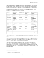
DI - Typical Input Circuit, Low Voltage DI I/O Circuit Diagram
 |
View all Motorola V186 manuals
Add to My Manuals
Save this manual to your list of manuals |
Page 19 highlights
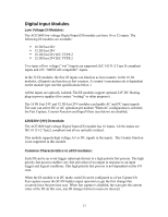
Digital Input Modules Each DI module can be switched by the user application program to Sleep Mode. In Sleep Mode, the module does not function and the power consumption is minimized. During Sleep mode, the user application program will get the predefined values (PDV) for each I/O. The DI module can be diagnosed and monitored using the STS Hardware Test utility. This test verifies that the module is operational, presents the module configuration and shows the actual value of each input. It is also possible to change the input filter setup temporarily for the duration of the Hardware Test. In the STS Hardware Test utility, it is possible to set the DI module to Freeze Mode. In this mode the user application program will get the predefined value of each input in the module, instead of the actual input value. Freeze mode enables testing the inputs while the user application program is running. Connection of a dry contact sensor to the low voltage DI module requires "wetting" the contact with a voltage. This can be done using the 24V DC floating plug-in power supplies that can be added to the module. The 24V can be also used to power "wet" sensors. ** The 24V can be also used to power "wet" sensors. (Low voltage only) Low Voltage DI I/O Circuit Diagram: DI - Typical Input Circuit DI Status + Full Diode 33V Bridge Rectifier - 6.5 mA Current Limiter 250Ω DI COM ** Available as of December 2007. 15
-
 1
1 -
2
-
3
-
4
-
5
-
6
-
7
-
8
-
9
-
10
-
11
-
12
-
13
-
 14
14 -
 15
15 -
 16
16 -
 17
17 -
 18
18 -
 19
19 -
 20
20 -
 21
21 -
 22
22 -
 23
23 -
 24
24 -
25
-
26
-
27
-
28
-
29
-
30
-
31
-
32
-
33
-
34
-
35
-
36
-
37
-
38
-
39
-
40
-
41
-
42
-
43
-
44
-
45
-
46
-
47
-
48
-
49
-
50
-
51
-
52
-
53
-
54
-
55
-
56
-
57
-
58
-
59
-
60
-
61
-
62
-
63
-
64
-
65
-
66
-
67
-
68
-
69
-
70
-
71
-
72
-
73
-
74
-
75
-
76
-
77
-
78
-
79
-
80
-
81
-
82
-
83
-
84
-
85
-
86
-
87
-
88
-
89
-
90
-
91
-
92
-
93
-
94
-
95
-
96
-
97
-
98
-
99
-
100
-
101
-
102
-
103
-
104
-
105
-
106
-
107
-
108
-
109
-
110
-
111
-
112
-
113
-
114
-
115
-
116
-
117
-
118
-
119
-
120
-
121
-
122
-
123
-
124
-
125
-
126
-
127
-
128
-
129
-
130
-
131
-
132
-
133
-
134
-
135
-
136
-
137
-
138
-
139
-
140
-
141
-
142
-
143
-
144
-
145
-
146
-
147
-
148
-
149
-
150
-
151
-
152
-
153
-
154
-
155
-
156
-
157
-
158
-
159
-
160
-
161
-
162
-
163
-
164
-
165
-
166
-
167
-
168
-
169
-
170
-
171
-
172
-
173
-
174
-
175
-
176
-
177
-
178
-
179
-
180
-
181
-
182
-
183
-
184
-
185
 |
 |
