Motorola V186 User Manual - Page 72
V4 = Vo - 0.15I1+I2+I3+I4 - 0.15I2+I3+I4 - 0.15I3+I4 - 0.15I4 - 0.15I4
 |
View all Motorola V186 manuals
Add to My Manuals
Save this manual to your list of manuals |
Page 72 highlights
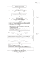
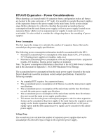
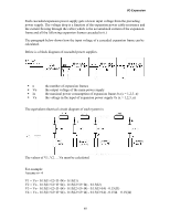
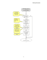
I/O Expansion Each cascaded expansion power supply gets a lower input voltage from the preceding power supply. The voltage drop is a function of the expansion power cable resistance and the current flowing through the cable (which is the accumulated current of the expansion frame and all the following expansion frames cascaded to it.) The paragraph below shows how the input voltage of a cascaded expansion frame can be calculated. Below is a block diagram of cascaded power supplies. ƒ n ƒ Vo ƒ Ix ƒ Vx the number of expansion frames the output voltage of the main power supply the maximal power consumption of expansion frame #x (x = 1,2,3..n) the voltage in the input of expansion power supply #x (x = 1,2,3..n) The equivalent electrical circuit diagram of such system is: The values of V1, V2.....Vn must be calculated. For example: Assume n= 4 V1 = Vo - 0.15(I1+I2+I3+I4) - 0.15(I1) V2 = Vo - 0.15(I1+I2+I3+I4) - 0.15(I2+I3+I4) - 0.15(I2) V3 = Vo - 0.15(I1+I2+I3+I4) - 0.15(I2+I3+I4) - 0.15(I3+I4) - 0.15(I3) V4 = Vo - 0.15(I1+I2+I3+I4) - 0.15(I2+I3+I4) - 0.15(I3+I4) - 0.15I4 - 0.15(I4) 68
-
 1
1 -
2
-
3
-
4
-
5
-
6
-
7
-
8
-
9
-
10
-
11
-
12
-
13
-
14
-
15
-
16
-
17
-
18
-
19
-
20
-
21
-
22
-
23
-
24
-
25
-
26
-
27
-
28
-
29
-
30
-
31
-
32
-
33
-
34
-
35
-
36
-
37
-
38
-
39
-
40
-
41
-
42
-
43
-
44
-
45
-
46
-
47
-
48
-
49
-
50
-
51
-
52
-
53
-
54
-
55
-
56
-
57
-
58
-
59
-
60
-
61
-
62
-
63
-
64
-
65
-
66
-
 67
67 -
 68
68 -
 69
69 -
 70
70 -
 71
71 -
 72
72 -
 73
73 -
 74
74 -
 75
75 -
 76
76 -
 77
77 -
78
-
79
-
80
-
81
-
82
-
83
-
84
-
85
-
86
-
87
-
88
-
89
-
90
-
91
-
92
-
93
-
94
-
95
-
96
-
97
-
98
-
99
-
100
-
101
-
102
-
103
-
104
-
105
-
106
-
107
-
108
-
109
-
110
-
111
-
112
-
113
-
114
-
115
-
116
-
117
-
118
-
119
-
120
-
121
-
122
-
123
-
124
-
125
-
126
-
127
-
128
-
129
-
130
-
131
-
132
-
133
-
134
-
135
-
136
-
137
-
138
-
139
-
140
-
141
-
142
-
143
-
144
-
145
-
146
-
147
-
148
-
149
-
150
-
151
-
152
-
153
-
154
-
155
-
156
-
157
-
158
-
159
-
160
-
161
-
162
-
163
-
164
-
165
-
166
-
167
-
168
-
169
-
170
-
171
-
172
-
173
-
174
-
175
-
176
-
177
-
178
-
179
-
180
-
181
-
182
-
183
-
184
-
185
 |
 |
