Motorola V186 User Manual - Page 14
I/O Modules, The I/O status LEDs in Digital Input DI and Digital Output
 |
View all Motorola V186 manuals
Add to My Manuals
Save this manual to your list of manuals |
Page 14 highlights
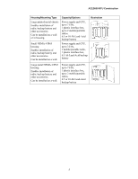
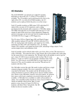
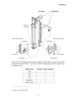
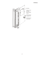
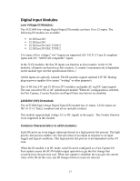
I/O Modules The ACE3600 RTU can include up to eight I/O modules, depending on the frame size. A variety of I/O modules is available. The I/O modules can be positioned in the slots to the right of the CPU. As with all ACE3600 modules, the I/O modules can be replaced while the power is on (hot swap.) Each I/O module includes an ERR status LED, individual I/O status LEDs, an array of I/O connectors, and a coding mechanism for the terminal cable connector or TB holder option. The ERR LED indicates an I/O module fault and errors. It will remain lit until all the errors have been eliminated. Diagnostic and error messages can be retrieved from the module using the ACE3600 STS Error Logger or SW Diagnostics. The I/O status LEDs in Digital Input (DI) and Digital Output (DO) modules indicate ON and OFF (LED lit when the I/O is ON.) In Analog Input (AI) modules, each input has two LEDs, indicating Overflow (OF) and Underflow (UF). In Analog Output (AO) modules, each output has three LEDs, indicating voltage output (Vout), current output (Iout), and calibration (Cal). Each I/O module can be ordered either with a set of two, three or four TB connectors or with a TB holder. TB connectors have a fixed female side on the module and a male plug for the sensor/device wire connection. The TB male side in all modules is screw type for up to 1mm (18 AWG) wire in modules with two/four TBs (3.5 mm pitch) or 1.6 mm (14 AWG) wire in modules with three TBs (5 mm pitch). Two TB extractor tools (FHN7063A) are provided for easy removal of TBs, one for modules with two/four TBs and one for modules with three TBs. The TB holder secures the male TBs neatly in place and forms a single connector plug per module. The wires connected to the TBs are concealed in the holder. The module and the TB holder provide a coding mechanism to prevent cabling errors. Ejector handles enable easy release of the TB holder connector from the module. An optional three-meter cable braid, completely wired with holder and cable, is available. A TB holder kit is available to enable self-assembly of cables. User assembled cables should use wires of up to 0.4mm (26 AWG) in modules with two/four TBs (3.5 mm pitch) or wires of up to 0.8 mm (20 AWG) in modules with three TBs (5 mm pitch). The TB holder kit does not include a cable. 10
-
 1
1 -
2
-
3
-
4
-
5
-
6
-
7
-
8
-
 9
9 -
 10
10 -
 11
11 -
 12
12 -
 13
13 -
 14
14 -
 15
15 -
 16
16 -
 17
17 -
 18
18 -
 19
19 -
20
-
21
-
22
-
23
-
24
-
25
-
26
-
27
-
28
-
29
-
30
-
31
-
32
-
33
-
34
-
35
-
36
-
37
-
38
-
39
-
40
-
41
-
42
-
43
-
44
-
45
-
46
-
47
-
48
-
49
-
50
-
51
-
52
-
53
-
54
-
55
-
56
-
57
-
58
-
59
-
60
-
61
-
62
-
63
-
64
-
65
-
66
-
67
-
68
-
69
-
70
-
71
-
72
-
73
-
74
-
75
-
76
-
77
-
78
-
79
-
80
-
81
-
82
-
83
-
84
-
85
-
86
-
87
-
88
-
89
-
90
-
91
-
92
-
93
-
94
-
95
-
96
-
97
-
98
-
99
-
100
-
101
-
102
-
103
-
104
-
105
-
106
-
107
-
108
-
109
-
110
-
111
-
112
-
113
-
114
-
115
-
116
-
117
-
118
-
119
-
120
-
121
-
122
-
123
-
124
-
125
-
126
-
127
-
128
-
129
-
130
-
131
-
132
-
133
-
134
-
135
-
136
-
137
-
138
-
139
-
140
-
141
-
142
-
143
-
144
-
145
-
146
-
147
-
148
-
149
-
150
-
151
-
152
-
153
-
154
-
155
-
156
-
157
-
158
-
159
-
160
-
161
-
162
-
163
-
164
-
165
-
166
-
167
-
168
-
169
-
170
-
171
-
172
-
173
-
174
-
175
-
176
-
177
-
178
-
179
-
180
-
181
-
182
-
183
-
184
-
185
 |
 |
