Motorola V186 User Manual - Page 138
to the RADIO 1/1 link, and the RTUs in zone 2 to the RADIO 1/2 link. RTU 15 should
 |
View all Motorola V186 manuals
Add to My Manuals
Save this manual to your list of manuals |
Page 138 highlights
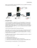
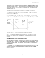
Communications The schematic representation of this system is shown below. The system assumes that the two nodes, RTU 15 and RTU 40, cannot "hear" each other. They communicate via the FEP, which is also a Store & Forward node. This system, therefore, consists of four zones and three nodes (RTU 15, RTU 40, and FIU). Any communication between RTUs in different zones passes through these three nodes. RADIO 1/3 RTU 15 RADIO 1/1 ZONE 1 RTU 1 RTU 2 FEP RADIO 1/4 RTU 40 RADIO 1/2 ZONE 2 RTU 1 RTU 2 In the above situation, three nodes with their accessible (logical) links should be defined. Using the STS site configuration, the RTUs in zone 1 should be configured to have access to the RADIO 1/1 link, and the RTUs in zone 2 to the RADIO 1/2 link. RTU 15 should be configured to have access to both RADIO 1/1 and RADIO 1/3 links, while RTU 40 should be configured to have access to both RADIO 1/2 and RADIO 1/4 links. The FEP is configured to have access to both RADIO 1/3 and RADIO 1/4 links. Assuming that the two nodes (RTU 15 and RTU 40) can "hear" each other, the result is a system consisting of three zones and two nodes, as shown in the following figure: RTU 15 RADIO 1/1 RTU 4 RTU 5 RADIO 1/3 FEP RTU 40 RADIO 1/2 RTU 1 RTU 2 134
-
 1
1 -
2
-
3
-
4
-
5
-
6
-
7
-
8
-
9
-
10
-
11
-
12
-
13
-
14
-
15
-
16
-
17
-
18
-
19
-
20
-
21
-
22
-
23
-
24
-
25
-
26
-
27
-
28
-
29
-
30
-
31
-
32
-
33
-
34
-
35
-
36
-
37
-
38
-
39
-
40
-
41
-
42
-
43
-
44
-
45
-
46
-
47
-
48
-
49
-
50
-
51
-
52
-
53
-
54
-
55
-
56
-
57
-
58
-
59
-
60
-
61
-
62
-
63
-
64
-
65
-
66
-
67
-
68
-
69
-
70
-
71
-
72
-
73
-
74
-
75
-
76
-
77
-
78
-
79
-
80
-
81
-
82
-
83
-
84
-
85
-
86
-
87
-
88
-
89
-
90
-
91
-
92
-
93
-
94
-
95
-
96
-
97
-
98
-
99
-
100
-
101
-
102
-
103
-
104
-
105
-
106
-
107
-
108
-
109
-
110
-
111
-
112
-
113
-
114
-
115
-
116
-
117
-
118
-
119
-
120
-
121
-
122
-
123
-
124
-
125
-
126
-
127
-
128
-
129
-
130
-
131
-
132
-
 133
133 -
 134
134 -
 135
135 -
 136
136 -
 137
137 -
 138
138 -
 139
139 -
 140
140 -
 141
141 -
 142
142 -
 143
143 -
144
-
145
-
146
-
147
-
148
-
149
-
150
-
151
-
152
-
153
-
154
-
155
-
156
-
157
-
158
-
159
-
160
-
161
-
162
-
163
-
164
-
165
-
166
-
167
-
168
-
169
-
170
-
171
-
172
-
173
-
174
-
175
-
176
-
177
-
178
-
179
-
180
-
181
-
182
-
183
-
184
-
185
 |
 |
