Motorola V186 User Manual - Page 18
Digital Input Modules, Feature, Parameter, Settings, Default Setting, Per Module, Input - features
 |
View all Motorola V186 manuals
Add to My Manuals
Save this manual to your list of manuals |
Page 18 highlights
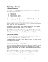
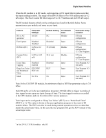
Digital Input Modules When the DI module is in DC mode, each input has a HW input filter to make sure that the input reading is stable. The range of the HW DI filter is 0 to 50.8 millisecond (in 0.2 mS steps). The Fast Counter DI filter range is 0 to 12.75 millisecond (in 0.05 mS steps). The DI module features which can be configured are listed in the table below. Some parameters are per module and some are per input. Feature DC or AC operation∗ Fast Capture DI Filter (DC) Parameter Settings AC/DC Disabled /Enabled 0-254 (x 0.2 mS) Counter Filter (DC) 0-255 (x 0.05 mS) Event Time Tagging Disabled/ Enabled Keep Last Value KLV/PDV and Predefined PDV=0/1 Value Mask No /Yes Default Setting DC Per Module/ Input Module Disabled Input 50 (10 mS) Module 20 (1 ms) Module Disabled KLV Input Input No Input Parameter Setup Location STS site configuration STS site configuration STS site configuration; 'C' User Program STS site configuration 'C' User Program User Program I/O link table User Program I/O link table User Program I/O link table Note: In the 120/230V DI module, the minimum effective DI Filter parameter value is 7.0 mSec. Each DI can be set in the user application program's I/O link table to trigger recording of time tagged events upon any input change of state. The time tagged events are recorded in the CPU memory and can be retrieved for various purposes. Each input can be configured to "Keep Last Value" (KLV) or to "Predefined Value" (PDV 0 or 1). This value is shown to the user application program in the event of DI module failure. The PDV can also be used during normal operation to force a value that masks the actual input value. In this case the user program will get the PDV instead of the actual input value. ∗ in Fast 24V IEC TYPE II modules -only DC 14
-
 1
1 -
2
-
3
-
4
-
5
-
6
-
7
-
8
-
9
-
10
-
11
-
12
-
 13
13 -
 14
14 -
 15
15 -
 16
16 -
 17
17 -
 18
18 -
 19
19 -
 20
20 -
 21
21 -
 22
22 -
 23
23 -
24
-
25
-
26
-
27
-
28
-
29
-
30
-
31
-
32
-
33
-
34
-
35
-
36
-
37
-
38
-
39
-
40
-
41
-
42
-
43
-
44
-
45
-
46
-
47
-
48
-
49
-
50
-
51
-
52
-
53
-
54
-
55
-
56
-
57
-
58
-
59
-
60
-
61
-
62
-
63
-
64
-
65
-
66
-
67
-
68
-
69
-
70
-
71
-
72
-
73
-
74
-
75
-
76
-
77
-
78
-
79
-
80
-
81
-
82
-
83
-
84
-
85
-
86
-
87
-
88
-
89
-
90
-
91
-
92
-
93
-
94
-
95
-
96
-
97
-
98
-
99
-
100
-
101
-
102
-
103
-
104
-
105
-
106
-
107
-
108
-
109
-
110
-
111
-
112
-
113
-
114
-
115
-
116
-
117
-
118
-
119
-
120
-
121
-
122
-
123
-
124
-
125
-
126
-
127
-
128
-
129
-
130
-
131
-
132
-
133
-
134
-
135
-
136
-
137
-
138
-
139
-
140
-
141
-
142
-
143
-
144
-
145
-
146
-
147
-
148
-
149
-
150
-
151
-
152
-
153
-
154
-
155
-
156
-
157
-
158
-
159
-
160
-
161
-
162
-
163
-
164
-
165
-
166
-
167
-
168
-
169
-
170
-
171
-
172
-
173
-
174
-
175
-
176
-
177
-
178
-
179
-
180
-
181
-
182
-
183
-
184
-
185
 |
 |
