Motorola V186 User Manual - Page 11
V Backup Battery, Overvoltage protection for CPU and I/Os - specifications
 |
View all Motorola V186 manuals
Add to My Manuals
Save this manual to your list of manuals |
Page 11 highlights
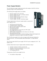
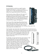
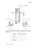
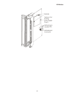
ACE3600 RTU Construction ƒ Short circuit protection outputs ƒ PS located on the leftmost slot of the frame ƒ Overvoltage protection for CPU and I/Os ƒ Reverse voltage protection Power supply modules with a battery option support a 6.5 or 10 Ah Lead-Acid battery. The power supply automatically switches to the backup battery as a 12V DC power source for the RTU and communications when the main AC or DC power source fails. Power supply modules with battery charger option charge the backup battery when not in use, and protect the battery from over-discharge. The charger performs battery tests/diagnostics, including controlled battery discharge, when requested by the user. If the battery is failed, the charger will not charge it and will send a failed status signal to the CPU. If the battery is remotely located, long battery cables can be used. The charging voltage of the Lead-Acid battery is controlled by the charger as a function of the battery temperature. The charging profile is set to comply with the temperaturecompensated float-voltage of the ACE3600 battery. A battery test can be performed on the Lead-Acid battery, either from the ACE3600 STS Hardware Test utility or from the user application program. The battery test includes disabling the battery charger, discharging the battery and measuring the capacitance. Note: An additional power supply module for use with I/O expansion frames is described in the Expansion Power Supply Module section below. 12V Backup Battery The ACE3600 backup 12V Lead-Acid battery provides backup for the main input power. The battery is available in two capacities: 6.5 Ah and 10 Ah. Switching from main input power to the battery and charging of the battery is performed by the ACE3600 power supply module. Sealed Lead-Acid technology batteries can be recharged and discharged at a temperature range of -30º to +60ºC. Storage and operating temperatures affect the battery capacity and lifespan. ACE3600 power supply modules include a special charging power supply designed to fit the specific temperature-compensated float-voltage-charging curve of the battery. 7
-
 1
1 -
2
-
3
-
4
-
5
-
 6
6 -
 7
7 -
 8
8 -
 9
9 -
 10
10 -
 11
11 -
 12
12 -
 13
13 -
 14
14 -
 15
15 -
 16
16 -
17
-
18
-
19
-
20
-
21
-
22
-
23
-
24
-
25
-
26
-
27
-
28
-
29
-
30
-
31
-
32
-
33
-
34
-
35
-
36
-
37
-
38
-
39
-
40
-
41
-
42
-
43
-
44
-
45
-
46
-
47
-
48
-
49
-
50
-
51
-
52
-
53
-
54
-
55
-
56
-
57
-
58
-
59
-
60
-
61
-
62
-
63
-
64
-
65
-
66
-
67
-
68
-
69
-
70
-
71
-
72
-
73
-
74
-
75
-
76
-
77
-
78
-
79
-
80
-
81
-
82
-
83
-
84
-
85
-
86
-
87
-
88
-
89
-
90
-
91
-
92
-
93
-
94
-
95
-
96
-
97
-
98
-
99
-
100
-
101
-
102
-
103
-
104
-
105
-
106
-
107
-
108
-
109
-
110
-
111
-
112
-
113
-
114
-
115
-
116
-
117
-
118
-
119
-
120
-
121
-
122
-
123
-
124
-
125
-
126
-
127
-
128
-
129
-
130
-
131
-
132
-
133
-
134
-
135
-
136
-
137
-
138
-
139
-
140
-
141
-
142
-
143
-
144
-
145
-
146
-
147
-
148
-
149
-
150
-
151
-
152
-
153
-
154
-
155
-
156
-
157
-
158
-
159
-
160
-
161
-
162
-
163
-
164
-
165
-
166
-
167
-
168
-
169
-
170
-
171
-
172
-
173
-
174
-
175
-
176
-
177
-
178
-
179
-
180
-
181
-
182
-
183
-
184
-
185
 |
 |
