Panasonic AG-HMX100 Operating Instructions - Page 15
Connector Area (Rear), AUDIO IN 1 to 4 L and R connectors - hd sdi
 |
View all Panasonic AG-HMX100 manuals
Add to My Manuals
Save this manual to your list of manuals |
Page 15 highlights
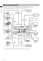
Overview Connector Area (Rear) For devices and signals which can be connected to each connector, see "System Configuration Examples" ( page 16) and "Example Connections with 3D Camera" ( pages Vol.2-22 to 24). NOTE • For the DVI-I IN connector and DVI-D IN connectors, shielded DVI cables with noise suppression core are recommended. • For transmitting HD-SDI signals via the SDI IN 1 to 4 connectors and SDI OUT connectors, cables equivalent or superior to the 5C-FB or 5C-FW cable are recommended. • When signals with the Copy Guard function applied are input to the HDMI IN, DVI-I IN or VIDEO IN connector, neither image nor sound is output (a black image appears). 1 2 3 4 5 67 8 9 DVI-I IN IN 1 SDI IN 1 2 3 4 PGM DVI-D OUT MULTI VIEW IN 2 SDI OUT MIC PGM PVW AUX MULTI VIEW PHONES VIDEO IN G/L ADV-REF GPI 1 2 L R L R L R AUDIO OUT 2 L R L R AUX IN L R L R 1 2 3 4 AUDIO IN AUDIO OUT 1 RS-232C TALLY SIGNAL GND ~AC IN 18 17 16 15 14 13 12 11 10 1 SDI IN 1 to 4 connectors 2 DVI-I IN connector ( pages 32, Vol.2-28) 3 HDMI IN 1, 2 connectors ( pages 17, 18) 4 DVI-D OUT connectors • PGM connector • MULTI VIEW connector 5 PHONES connector ( page 33) 6 RS-232C connector ( page Vol.2-28) 7 TALLY connector ( page Vol.2-29) 8 AC IN power socket 9 GND terminal 10 AUDIO OUT 2 L and R connectors (unbalanced output) 11 AUDIO OUT 1 L and R connectors (balanced output) 12 AUX IN L and R connectors 13 MIC connector 14 GPI connector ( page Vol.2-26) 15 SDI OUT connectors • PGM connector • PVW connector • AUX connector • MULTI VIEW connector 16 G/L connector ( page Vol.2-28) ADV-REF connector ( page Vol.2-28) 17 AUDIO IN 1 to 4 L and R connectors 18 VIDEO IN 1, 2 connectors 15
-
 1
1 -
2
-
3
-
4
-
5
-
6
-
7
-
8
-
9
-
 10
10 -
 11
11 -
 12
12 -
 13
13 -
 14
14 -
 15
15 -
 16
16 -
 17
17 -
 18
18 -
 19
19 -
 20
20 -
21
-
22
-
23
-
24
-
25
-
26
-
27
-
28
-
29
-
30
-
31
-
32
-
33
-
34
-
35
-
36
-
37
-
38
-
39
-
40
-
41
-
42
-
43
-
44
-
45
-
46
-
47
-
48
 |
 |
