Panasonic AG-HMX100 Operating Instructions - Page 16
Basic Operation, System Configuration Examples, SD Video Processing System - video output
 |
View all Panasonic AG-HMX100 manuals
Add to My Manuals
Save this manual to your list of manuals |
Page 16 highlights
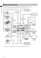
Basic Operation Basic Operation This chapter describes the initial setup operation for video processing and audio mixing, and the operation of selecting video and audio sources, and setting the basic video switching effects. System Configuration Examples This unit can be connected to video equipment including cameras, P2 devices and VTRs to digitally process video and sound input sources. The following shows the connection examples of this unit with external equipment in three types of system configurations: a system for processing SD video, a system for processing HD video, and a system operated from an external controller. SD Video Processing System System camera Loopthrough Advanced reference signal*1 Signal generator Program output System camera SDI (video and audio) input G/L external sync signal*1 Preview output ADV-REF G/L Professional-use VTR SDI IN 1 SDI output AG-HMX100P/HMX100E SDI OUT PGM Multi- view Professional-use output monitor Termination SDI (video and audio) input SDI IN 2 SDI IN 3 SDI IN 4 P2 mobile Composite input VIDEO IN 1 VIDEO IN 2 Composite input Professional-use video camera MIC AUDIO IN MIC input SDI OUT PVW SDI OUT MULTI VIEW SDI OUT AUX Program output DVI-D OUT PGM DVI-I IN DVI-D OUT MULTI VIEW MultiDVI-D output view output DVI-I input Analog PC audio input AUX output Professional-use projector Home-use television Professional-use video camera MIC Professional-use audio equipment *1 Advanced reference signal or G/L external sync signal need not necessarily be connected. 16
-
 1
1 -
2
-
3
-
4
-
5
-
6
-
7
-
8
-
9
-
10
-
 11
11 -
 12
12 -
 13
13 -
 14
14 -
 15
15 -
 16
16 -
 17
17 -
 18
18 -
 19
19 -
 20
20 -
 21
21 -
22
-
23
-
24
-
25
-
26
-
27
-
28
-
29
-
30
-
31
-
32
-
33
-
34
-
35
-
36
-
37
-
38
-
39
-
40
-
41
-
42
-
43
-
44
-
45
-
46
-
47
-
48
 |
 |
