Panasonic AG-HMX100 Operating Instructions-Advanced - Page 22
Switching 3D Video, Example Connections with 3D Camera - ag hmx100p
 |
View all Panasonic AG-HMX100 manuals
Add to My Manuals
Save this manual to your list of manuals |
Page 22 highlights
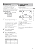
Chapter 3 Switching 3D Video When two different types of video for the left eye (L channel) and right eye (R channel) are monitored in the overlay state, adjustment is made for allowing the left eye and right eye to view the L-channel video and R-channel video, respectively, for example, wearing 3D glasses. This adjustment enables the brain to recognize the images on video as stereoscopic images. When the parallax (distance between left and right eyes) is virtually increased, a 3D appearance and a sense of depth are enhanced. When 3D video is used as the input source to this unit, two input connectors are paired to input one video for the left eye and the other for the right eye. Chapter 3 Switching 3D Video Example Connections with 3D Camera This section shows examples of systems in which this unit and 3D camera are connected to create 3D video using each input video for the L and R channels. The following are three system examples: • System for displaying the program output and multi-view output of this unit on a single monitor (simultaneous display of L and R channels) • System for individually displaying the program output and multi-view output on different monitors (use of SIDE BY SIDE signal) • System for using video from four cameras as the input sources to two units of AG-HMX100P/HMX100E NOTE • The 3D video production systems shown below cannot perform preview output. AUX output can be used only for input source check. Of the video switching effects, only cut can be executed. • When [3DFORMAT] is set to [1080/23PsF] in 3D mode, this unit cannot be synchronized with an external signal generator. System for Monitoring Program Output as L channel and Multi-view Output as R Channel (Simultaneous Display of L and R Channels) SDI input 1 and SDI input 2 are paired to be used as L-channel and R-channel input sources, respectively. SDI input 3 and SDI input 4 are paired to be used as L-channel and R-channel input sources, respectively. Program output and multi-view output are paired to be used as L-channel and R-channel outputs. 3D mode is set to [MODE1] ( page 25). Advanced reference signal*1 L L R Professional-use 3D-integrated camera SDI (video and audio) input ADV-REF SDI IN 1 Program output R SDI output SDI OUT PGM Professional-use 3D monitor Multi-view output SDI OUT MULTI VIEW SDI IN 2 L-channel side SDI IN 3 Professional-use camera SDI IN 4 Loopthrough Program output L DVI-D OUT PGM Multi-view output AG-HMX100P/HMX100E DVI-D OUT MULTI VIEW DVI-D output Professional-use projector Termination Professional-use camera R-channel side R Professional-use projector *1 Advanced reference signal need not necessarily be connected. 22
-
 1
1 -
2
-
3
-
4
-
5
-
6
-
7
-
8
-
9
-
10
-
11
-
12
-
13
-
14
-
15
-
16
-
 17
17 -
 18
18 -
 19
19 -
 20
20 -
 21
21 -
 22
22 -
 23
23 -
 24
24 -
 25
25 -
 26
26 -
 27
27 -
28
-
29
-
30
-
31
-
32
-
33
-
34
-
35
-
36
-
37
 |
 |