Panasonic AG-HMX100 Operating Instructions-Advanced - Page 29
Setting [RS-232C
 |
View all Panasonic AG-HMX100 manuals
Add to My Manuals
Save this manual to your list of manuals |
Page 29 highlights
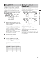
Chapter 4 Operating Environment Setting TALLY connector Open collector output connector for the tally lamp. When video of input source 1, 2, 3, 4, 5, 6, 7 or 8 is being used, the tally signal is output. 54321 9876 Pin No. 1 2 3 4 5 6 7 8 9 Signal Input source 1 Input source 2 Input source 3 Input source 4 Input source 5 Input source 6 Input source 7 Input source 8 GND AG-HMX100P/HMX100E Tally output (Max. 50 mA) GND Max. 35 V Talley LED Tally connection example The Tally signal is output with max. 35 V and max. 50 mA. Setting [RS-232C] This section describes the settings required for operating this unit from an external controller via the RS-232C interface. The RS-232C interface is also used to operate a projector from this unit. Rotary 1 Rotary 2 Rotary 3 Rotary 4 Rotary 5 RS-232C B. RATE DATA L. PARITY 38.4k 8BITS NONE PJ 9.6k 19.2k 38.4k 115.2k 8BITS 7BITS NONE ODD EVEN PJ RS-232C To set the communication rate Set [B. RATE] using the rotary 2 control. The following speeds can be selected. Setting [9.6 k] [19.2 k] [38.4 k] [115.2 k] Baud Rate 9600 bps 19200 bps 38400 bps 115200 bps The factory default setting is [9.6 k]. To set the data length Set [DATA L.] to [8BITS] or [7BITS] using the rotary 3 control. The factory default setting is [8BITS]. To set the communication parity Set [PARITY] to [NONE] (not set), [ODD] (odd bit), or [EVEN] (even bit) using the rotary 4 control. To select the communication mode [PJ] (projector) and [RS-232C] can be selected with the rotary 5 control. If [PJ] is selected, the Projector Setting screen appears when the PROJECTOR/REMOTE button is set to ON, enabling operation of a Panasonic projector from this unit. Projector setting screen The status of the projector connected to this unit is displayed. POS. X 128 Y 128 Z 512 EVENT ME TIME 00 E 02:00 F PATTERN 0056 INT WHT PROJECTOR *** POWER : OFF SHUTTER : OFF POWER SHUTTER OFF OFF Appears during projector monitoring. When the projector is not compatible with the communication system of this unit or the unit cannot obtain any information due to differences in the communication protocol, "---" appears for [POWER] and [SHUTTER]. In addition, "---" appears for [SHUTTER] when the projector power is off. 29
-
 1
1 -
2
-
3
-
4
-
5
-
6
-
7
-
8
-
9
-
10
-
11
-
12
-
13
-
14
-
15
-
16
-
17
-
18
-
19
-
20
-
21
-
22
-
23
-
 24
24 -
 25
25 -
 26
26 -
 27
27 -
 28
28 -
 29
29 -
 30
30 -
 31
31 -
 32
32 -
 33
33 -
 34
34 -
35
-
36
-
37
 |
 |
