Panasonic PT-D7700U-K Dlp Projector - English/ French - Page 14
Side-mounted, connection terminals, MIN4-pin DIN.
 |
UPC - 791871111000
View all Panasonic PT-D7700U-K manuals
Add to My Manuals
Save this manual to your list of manuals |
Page 14 highlights
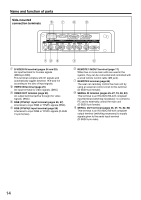
Name and function of parts Side-mounted connection terminals IN OUT REMOTE 1 REMOTE 2 S-VIDEO IN VIDEO IN OUT R/PR RS-232C (G) / RS-422 (R) RS-232C (G) / RS-422 (R) IN OUT RGB 1 IN G/Y B/PB SYNC/HD VD SERIAL RGB 2 IN S-VIDEO IN terminal (pages 24 and 25) An input terminal for S-video signals (MIN4-pin DIN). This terminal complies with S1 signals and automatically toggles between 16:9 and 4:3 according to the size of input signals. VIDEO IN terminal (page 25) An input terminal for video signals. (BNC) VIDEO OUT terminal (page 25) An output terminal (active through) for video signals. (BNC) RGB (YPBPR)1 input terminal (pages 26, 27) A terminal to input RGB or YPBPR signals (BNC). RGB (YPBPR)2 input terminal (page 26) A terminal to input RGB or YPBPR signals (D-SUB 15-pin female). REMOTE1 lN/OUT terminal (page 17) When two or more main units are used in the system, they can be connected and controlled with a wired remote control cable (M3 jack). REMOTE2 terminal (page 84) The user can remotely control the main unit by using an external control circuit to this terminal (D-SUB 9-pin female). SERIAL IN terminal (pages 25-27, 74, 82, 83) This terminal is an RS-232C/RS-422 compliant input terminal (switching necessary) to connect a PC and to externally control the main unit (D-SUB 9-pin female). SERIAL OUT terminal (pages 26, 27, 74, 82, 83) This terminal is an RS-232C/RS-422 compliant output terminal (switching necessary) to supply signals given to the serial input terminal (D-SUB 9-pin male). 14
-
 1
1 -
2
-
3
-
4
-
5
-
6
-
7
-
8
-
 9
9 -
 10
10 -
 11
11 -
 12
12 -
 13
13 -
 14
14 -
 15
15 -
 16
16 -
 17
17 -
 18
18 -
 19
19 -
20
-
21
-
22
-
23
-
24
-
25
-
26
-
27
-
28
-
29
-
30
-
31
-
32
-
33
-
34
-
35
-
36
-
37
-
38
-
39
-
40
-
41
-
42
-
43
-
44
-
45
-
46
-
47
-
48
-
49
-
50
-
51
-
52
-
53
-
54
-
55
-
56
-
57
-
58
-
59
-
60
-
61
-
62
-
63
-
64
-
65
-
66
-
67
-
68
-
69
-
70
-
71
-
72
-
73
-
74
-
75
-
76
-
77
-
78
-
79
-
80
-
81
-
82
-
83
-
84
-
85
-
86
-
87
-
88
-
89
-
90
-
91
-
92
-
93
-
94
-
95
-
96
-
97
-
98
-
99
-
100
-
101
-
102
-
103
-
104
-
105
-
106
-
107
-
108
-
109
-
110
-
111
-
112
-
113
-
114
-
115
-
116
 |
 |
