Panasonic PT-D7700U-K Dlp Projector - English/ French - Page 66
How To Switch The Input Impedance (signal Level) Of The Synchronization Signal
 |
UPC - 791871111000
View all Panasonic PT-D7700U-K manuals
Add to My Manuals
Save this manual to your list of manuals |
Page 66 highlights
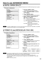
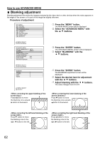
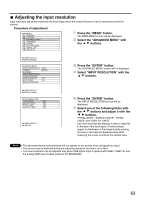
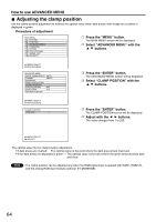
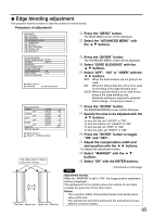
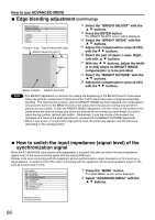
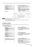
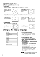
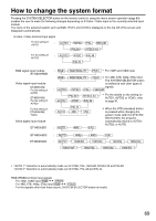
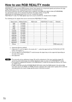
How to use ADVANCED MENU Edge blending adjustment (continuing) BRIGHT ADJUST BRIGHT INSIDE 6 BRIGHT OUTSIDE 6 UPPER 0 LOWER 0 LEFT 0 RIGHT 0 Projection range Edge blending width (right) BRIGHT adjustment (right) Marker BRIGHT INSIDE BRIGHT OUTSIDE Select the "BRIGHT ADJUST" with the buttons. Press the ENTER button. The BRIGHT ADJUST screen will be displayed. Select the "BRIGHT INSIDE" with the buttons. Adjust the compensation value (0-255) with the buttons. Select the part of Upper, Lower, Right, Left with buttons. With the buttons, adjust the width (0 to 255) where no BRIGHT INSIDE compensation is to be provided. Select the "BRIGHT OUTSIDE" with the buttons. Adjust the compensation value (0-255) with the buttons. Note • The BRIGHT adjustment is a function for making the brightening of the BRIGHT level in those areas where the pictures overlap less conspicuous when multi-screens have been configured using edge blending. The optimal point is where, after the BRIGHT INSIDE has been adjusted, the compensation amount is the same for the BRIGHT levels in the areas where the pictures overlap and where the pictures do not overlap. If, after the BRIGHT INSIDE adjustment, only the vicinity of the borders of the areas where the pictures overlap and where the pictures do not overlap becomes bright, proceed to adjust the top, bottom, left and right widths. Alternatively, if only the vicinity of the borders has darkened as a result of the width adjustments, proceed with the BRIGHT OUTSIDE adjustment. • When a rear screen or screen with a high gain is used, the joints may appear to be discontinuous depending on the viewing position. How to switch the input impedance (signal level) of the synchronization signal When the ET-MD95RGB input module (sold separately) is mounted, the user can switch the input impedance (signal level) of the synchronization signal with the analog RGB input. Choose 75 Ω when connecting with the equipment whose synchronization output impedance is 75 Ω such as a signal selector, or switch to HI-Z (TTL) when connecting with the equipment whose synchronization output is TTL such as a video card of a PC. MAIN MENU PICTURE POSITION ADVANCED MENU LANGUAGE OPTION TEST PATTERN SIGNAL LIST SECURITY Press the "MENU" button. The MAIN MENU screen will be displayed. Select "ADVANCED MENU" with the buttons. :MENU SELECT ENTER:SUB MENU 66
-
 1
1 -
2
-
3
-
4
-
5
-
6
-
7
-
8
-
9
-
10
-
11
-
12
-
13
-
14
-
15
-
16
-
17
-
18
-
19
-
20
-
21
-
22
-
23
-
24
-
25
-
26
-
27
-
28
-
29
-
30
-
31
-
32
-
33
-
34
-
35
-
36
-
37
-
38
-
39
-
40
-
41
-
42
-
43
-
44
-
45
-
46
-
47
-
48
-
49
-
50
-
51
-
52
-
53
-
54
-
55
-
56
-
57
-
58
-
59
-
60
-
 61
61 -
 62
62 -
 63
63 -
 64
64 -
 65
65 -
 66
66 -
 67
67 -
 68
68 -
 69
69 -
 70
70 -
 71
71 -
72
-
73
-
74
-
75
-
76
-
77
-
78
-
79
-
80
-
81
-
82
-
83
-
84
-
85
-
86
-
87
-
88
-
89
-
90
-
91
-
92
-
93
-
94
-
95
-
96
-
97
-
98
-
99
-
100
-
101
-
102
-
103
-
104
-
105
-
106
-
107
-
108
-
109
-
110
-
111
-
112
-
113
-
114
-
115
-
116
 |
 |
