Panasonic PT-D7700U-K Dlp Projector - English/ French - Page 63
Adjusting The Input Resolution, Advanced Menu
 |
UPC - 791871111000
View all Panasonic PT-D7700U-K manuals
Add to My Manuals
Save this manual to your list of manuals |
Page 63 highlights
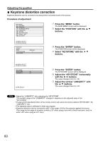
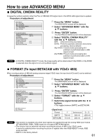
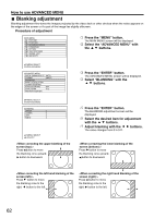
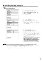
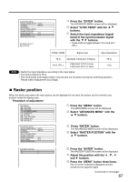
Adjusting the input resolution Input resolution adjustment achieves the best image when the screen flickers or halo is observed around the contour. Procedure of adjustment MAIN MENU PICTURE POSITION ADVANCED MENU LANGUAGE OPTION TEST PATTERN SIGNAL LIST SECURITY Press the "MENU" button. The MAIN MENU screen will be displayed. Select the "ADVANCED MENU" with the buttons. :MENU SELECT ENTER:SUB MENU ADVANCED MENU DIGITAL CINEMA REALITY AUTO FORMAT SMPTE BLANKING INPUT RESOLUTION CLAMP POSITION EDGE BLENDING OFF SYNC.TERM 75 RASTER POSITION Press the "ENTER" button. The ADVANCED MENU screen will be displayed. Select "INPUT RESOLUTION" with the buttons. :MENU SELECT ENTER:SUB MENU INPUT RESOLUTION TOTAL DOTS DISPLAY DOTS TOTAL LINES DISPLAY LINES 1056 832 666 624 :MENU SELECT :ADJUST Press the "ENTER" button. The INPUT RESOLUTION screen will be displayed. Select one of the following items with the buttons and adjust it with the buttons. "TOTAL DOTS", "DISPLAY DOTS", "TOTAL LINES" and "DISPLAY LINES" Each item automatically displays a value in response to the type of the input signal. If vertical stripes appear on the screen or the image is partly missing, increase or decrease the displayed value while observing the screen to achieve the optimal value. Note • The abovementioned vertical stripes will not appear on the screen when all signals are input. • The picture may be distorted during the adjusting operation, but this is not a fault. • The input resolution can be adjusted only when RGB signal input is applied with RGB1, RGB2 IN, and the analog RGB input module (optional: ET-MD95RGB). 63
-
 1
1 -
2
-
3
-
4
-
5
-
6
-
7
-
8
-
9
-
10
-
11
-
12
-
13
-
14
-
15
-
16
-
17
-
18
-
19
-
20
-
21
-
22
-
23
-
24
-
25
-
26
-
27
-
28
-
29
-
30
-
31
-
32
-
33
-
34
-
35
-
36
-
37
-
38
-
39
-
40
-
41
-
42
-
43
-
44
-
45
-
46
-
47
-
48
-
49
-
50
-
51
-
52
-
53
-
54
-
55
-
56
-
57
-
 58
58 -
 59
59 -
 60
60 -
 61
61 -
 62
62 -
 63
63 -
 64
64 -
 65
65 -
 66
66 -
 67
67 -
 68
68 -
69
-
70
-
71
-
72
-
73
-
74
-
75
-
76
-
77
-
78
-
79
-
80
-
81
-
82
-
83
-
84
-
85
-
86
-
87
-
88
-
89
-
90
-
91
-
92
-
93
-
94
-
95
-
96
-
97
-
98
-
99
-
100
-
101
-
102
-
103
-
104
-
105
-
106
-
107
-
108
-
109
-
110
-
111
-
112
-
113
-
114
-
115
-
116
 |
 |
