Panasonic PT-D7700U-K Dlp Projector - English/ French - Page 37
CONNECTING SIGNALS TO THE DVI SIGNAL INPUT MODULE, DVI-D input module optional, Pin No., Signal
 |
UPC - 791871111000
View all Panasonic PT-D7700U-K manuals
Add to My Manuals
Save this manual to your list of manuals |
Page 37 highlights
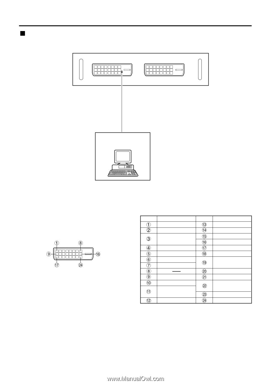
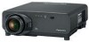
Connecting signals to the DVI signal input module DVI-D input module (optional) ET-MD75DV DVI Module DVI-D IN ET-MD75DV DVI-D OUT DVI signal PC with DVI output • Pin assignments and signal names of DVI-D input terminal are listed in the table at right (terminal for TMDS-equipped PC). External view • The DVI-D signal input module supports only a single link. Pin No. Signal TMDS data 2- TMDS data 2+ TMDS data 2 / 4 shield (T.M.D.S data 4-) (T.M.D.S data 4+) DDC clock DDC data T.M.D.S data 1- T.M.D.S data 1+ T.M.D.S data 1/3 shield (T.M.D.S data 3-) Pin No. Signal (T.M.D.S data 3+) +5V Ground Hot plug detection T.M.D.S data 0- T.M.D.S data 0+ T.M.D.S data 0/5 shield (T.M.D.S data 5-) (T.M.D.S data 5+) T.M.D.S clock shield T.M.D.S clock+ T.M.D.S clock- 37
-
 1
1 -
2
-
3
-
4
-
5
-
6
-
7
-
8
-
9
-
10
-
11
-
12
-
13
-
14
-
15
-
16
-
17
-
18
-
19
-
20
-
21
-
22
-
23
-
24
-
25
-
26
-
27
-
28
-
29
-
30
-
31
-
 32
32 -
 33
33 -
 34
34 -
 35
35 -
 36
36 -
 37
37 -
 38
38 -
 39
39 -
 40
40 -
 41
41 -
 42
42 -
43
-
44
-
45
-
46
-
47
-
48
-
49
-
50
-
51
-
52
-
53
-
54
-
55
-
56
-
57
-
58
-
59
-
60
-
61
-
62
-
63
-
64
-
65
-
66
-
67
-
68
-
69
-
70
-
71
-
72
-
73
-
74
-
75
-
76
-
77
-
78
-
79
-
80
-
81
-
82
-
83
-
84
-
85
-
86
-
87
-
88
-
89
-
90
-
91
-
92
-
93
-
94
-
95
-
96
-
97
-
98
-
99
-
100
-
101
-
102
-
103
-
104
-
105
-
106
-
107
-
108
-
109
-
110
-
111
-
112
-
113
-
114
-
115
-
116
 |
 |