Samsung SCX4521F Service Manual - Page 37
FUSER AC POWER CONTROL, Output Control Signal BIAS-PWM : Active Low PWM signal for controlling MHV
 |
UPC - 635753616040
View all Samsung SCX4521F manuals
Add to My Manuals
Save this manual to your list of manuals |
Page 37 highlights
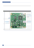
System Overview (c)Developing Voltage (DEV) - Input Voltage : 24V DC +15% / -10% (21.6V~27.6V) - Output Voltage: -350V 20V (50 Load) - Output Voltage Fluctuation range: PWM Control - Input contrast of the output stability degree : 5 %orless - Loading contrast : 5 %orless - Output Voltage Rising Time : 50 ms Max - Output Voltage Falling Time : 50 ms Max - Output Loading range : 10 ~1000 - Output Control Signal (BIAS-PWM) : Active Low PWM signal for controlling MHV (d) Supply - Output Voltage : -550V 50V(50 Load) - Input contrast of the output stability degree : under 5 % - Loading contrast : 5 %orless - Output Voltage Rising Time : 50 ms Max - Output Voltage Falling Time : 50 ms Max - Output Loading range : 10 ~ 1000 - Output Control Signal (BIAS-PWM) : Active Low PWM signal for controlling MHV 3.7 FUSER AC POWER CONTROL The Fuser(HEAT LAMP) gets heat from AC power. The AC power controls the switch with the Triac, a semiconductor switch. The 'ON/OFF control' is operated when the gate of the Triac is turned on/off by Phototriac (insulting part). In other words, the AC control part is passive circuit, so it turns the heater on/off with taking signal from engine control part. When the 'HEATERON' signal is turned on at engine,the LED of PC102 (Photo Triac) takes the voltage and flashes. From the flashing light, the Triac part (light receiving part) takes the voltage,and the voltage is supplied to the gate of Triac and flows into the Triac. As a result, the AC current flows in the heat lamp, and heat is occurred. On the other hand, when the signal is off, the PC102 is off, the voltage is cut off at the gate of Triac, the Triac becomes off, and then the heat lamp is turned off. 1) Triac feature : 12A, 600V SWITCHING 2) Phototriac Coupler (PC102) - Turn OnIf Current : 15mA~50mA(Design : 16mA) - High Repetive Peak Off State Voltage : Min 600V Samsung Electronics Service Manual 3-15
-
 1
1 -
2
-
3
-
4
-
5
-
6
-
7
-
8
-
9
-
10
-
11
-
12
-
13
-
14
-
15
-
16
-
17
-
18
-
19
-
20
-
21
-
22
-
23
-
24
-
25
-
26
-
27
-
28
-
29
-
30
-
31
-
 32
32 -
 33
33 -
 34
34 -
 35
35 -
 36
36 -
 37
37 -
 38
38 -
 39
39 -
 40
40 -
 41
41 -
 42
42 -
43
-
44
-
45
-
46
-
47
-
48
-
49
-
50
-
51
-
52
-
53
-
54
-
55
-
56
-
57
-
58
-
59
-
60
-
61
-
62
-
63
-
64
-
65
-
66
-
67
-
68
-
69
-
70
-
71
-
72
-
73
-
74
-
75
-
76
-
77
-
78
-
79
-
80
-
81
-
82
-
83
-
84
-
85
-
86
-
87
-
88
-
89
-
90
-
91
-
92
-
93
-
94
-
95
-
96
-
97
-
98
-
99
-
100
-
101
-
102
-
103
-
104
-
105
-
106
-
107
-
108
-
109
-
110
-
111
-
112
-
113
-
114
-
115
-
116
-
117
-
118
-
119
-
120
-
121
-
122
-
123
-
124
-
125
-
126
-
127
-
128
-
129
-
130
-
131
-
132
-
133
-
134
-
135
-
136
-
137
-
138
-
139
-
140
-
141
-
142
-
143
-
144
-
145
-
146
-
147
-
148
-
149
-
150
-
151
-
152
-
153
-
154
 |
 |
