TEAC TN-5BB Owners Manual English Francais Espanol Deutsch Italiano Nederlands - Page 9
Cartridge alignment (overhang adjustment), Place the Cartridge Alignment Gauge
 |
View all TEAC TN-5BB manuals
Add to My Manuals
Save this manual to your list of manuals |
Page 9 highlights
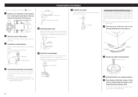
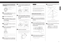
When installing a new cartridge or headshell on the TN-5BB, use the Cartridge Alignment Gauge to adjust the cartridge attachment position so that tracking error is minimized. Cartridge Alignment Gauge overview Use the template included with this product, or download the PDF from our website (https://teac.jp/int/product/tn-5bb/) and print it at actual size. After printing, carefully open a hole for the spindle, or use a utility knife to cut a cross into the spindle hole on the template. ATTENTION oo In order to prevent the stylus from becoming caught and causing damage, print on photo paper, glossy paper or other paper with a smooth surface. oo After printing the PDF, confirm that the distance between the center of the spindle hole and B is exactly 60 mm. If this distance is incorrect, printing was not at actual size, so this cannot be used to attach the cartridge at the correct position. Vertical guideline Vertical guideline Confirm that this length is 60 mm. Hole for spindle NOTE oo The vertical and horizontal lines are guidelines. oo The distance from the tonearm rotation central axis (tonearm pivot) to the center of the record is called the "pivot-to-spindle distance". The distance from the tonearm pivot to the cartridge stylus tip is called the "effective length". The difference between the two is the overhang length. Only this overhang length is adjusted with basic cartridge adjustment. Using this adjustment tool, however, the cartridge attachment position and angle can be adjusted more precisely, realizing a setup that suppresses tracking error even more. Cartridge alignment (overhang adjustment) Cartridge attachment explanation Temporarily fix the cartridge in position as explained in the previous "Changing the cartridge" section. When adjusting the cartridge position, move the cartridge along the screw holes in alignment with the central axis of the cantilever and headshell. (See the illustration below.) d: outward, e: inward Central axis oo The sides of the cartridge and the cantilever might not be parallel due to individual differences. This might be a slight inclination, but it cannot be ignored when making this adjustment, so align the central axis to that of the cantilever. oo To enable precise adjustment of the cartridge position, partially tighten the screws used to attach the cartridge to the headshell to hold it in place temporarily. Tightening the screws too much will prevent adjustment of the cartridge position. 1 Place the Cartridge Alignment Gauge on the turntable so that the spindle goes through its spindle hole. 3 Make precise adjustments to the cartridge attachment position so that the stylus tip and point A are at the same position. Refer to "Cartridge attachment explanation" for the relationship between the positions of the cartridge and the headshell. 4 Move the Cartridge Alignment Gauge and the tonearm to move the stylus tip to the point B position. 2 Move the Cartridge Alignment Gauge and the tonearm to find the position where the vertical line that passes through point A and the central axis of the headshell match. 5 If the headshell is parallel to the guide- line, proceed to the next step. If it is not parallel, refer to the illustration below and repeat adjustments from step 2. The overhang is too large. Move the cartridge inward. The overhang is too small. Move the cartridge outward. 6 Tighten the screws firmly, taking care not to shift the cartridge position. 7 Balance the tonearm and adjust the tracking force. Follow the procedures in "Balancing the tonearm and adjusting the tracking force" on page 5 9 ENGLISH
-
 1
1 -
2
-
3
-
 4
4 -
 5
5 -
 6
6 -
 7
7 -
 8
8 -
 9
9 -
 10
10 -
 11
11 -
 12
12 -
 13
13 -
 14
14 -
15
-
16
-
17
-
18
-
19
-
20
-
21
-
22
-
23
-
24
-
25
-
26
-
27
-
28
-
29
-
30
-
31
-
32
-
33
-
34
-
35
-
36
-
37
-
38
-
39
-
40
-
41
-
42
-
43
-
44
-
45
-
46
-
47
-
48
-
49
-
50
-
51
-
52
-
53
-
54
-
55
-
56
-
57
-
58
-
59
-
60
-
61
-
62
-
63
-
64
-
65
-
66
-
67
-
68
-
69
-
70
-
71
-
72
-
73
-
74
-
75
-
76
-
77
-
78
-
79
-
80
-
81
-
82
-
83
-
84
 |
 |
