Yamaha CLP-380 Owner's Manual - Page 117
Keyboard Stand Assembly
 |
View all Yamaha CLP-380 manuals
Add to My Manuals
Save this manual to your list of manuals |
Page 117 highlights
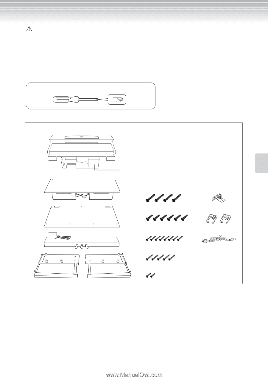
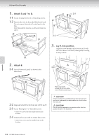
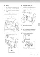
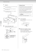
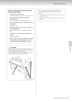
Keyboard Stand Assembly CAUTION • Be careful not to confuse parts, and be sure to install all parts in the correct direction. Please assemble in accordance with the sequence given below. • Assembly should be carried out by at least two persons. • Be sure to use the correct screw size, as indicated below. Use of incorrect screws can cause damage. • Assemble the stand on a flat floor with ample space. • Be sure to tighten up all screws upon completing assembly of each unit. • To disassemble, reverse the assembly sequence given below. Have a Phillips-head (+) screwdriver of the appropriate size ready. Remove all parts from the box. Confirm that all parts shown in the illustration are provided. A Connector panel AC IN Styrofoam pads Take out the styrofoam pads, and place A on top of the pads. Position the styrofoam pads to protect the connector panel at the bottom of A and the AC IN. B 6 x 25mm long screws x 4 Headphone hanger C Pedal cord D E F 6 x 16mm short screws x 6 Cord holders x 2 4 x 14mm thin screws x 8 AC power cord 4 x 20mm tapping screws x 5 4 x 10mm thin screws x 2 (The shape of plug differs depending on locale.) Appendix CLP-380 Owner's Manual 117
-
 1
1 -
2
-
3
-
4
-
5
-
6
-
7
-
8
-
9
-
10
-
11
-
12
-
13
-
14
-
15
-
16
-
17
-
18
-
19
-
20
-
21
-
22
-
23
-
24
-
25
-
26
-
27
-
28
-
29
-
30
-
31
-
32
-
33
-
34
-
35
-
36
-
37
-
38
-
39
-
40
-
41
-
42
-
43
-
44
-
45
-
46
-
47
-
48
-
49
-
50
-
51
-
52
-
53
-
54
-
55
-
56
-
57
-
58
-
59
-
60
-
61
-
62
-
63
-
64
-
65
-
66
-
67
-
68
-
69
-
70
-
71
-
72
-
73
-
74
-
75
-
76
-
77
-
78
-
79
-
80
-
81
-
82
-
83
-
84
-
85
-
86
-
87
-
88
-
89
-
90
-
91
-
92
-
93
-
94
-
95
-
96
-
97
-
98
-
99
-
100
-
101
-
102
-
103
-
104
-
105
-
106
-
107
-
108
-
109
-
110
-
111
-
 112
112 -
 113
113 -
 114
114 -
 115
115 -
 116
116 -
 117
117 -
 118
118 -
 119
119 -
 120
120 -
 121
121 -
 122
122 -
123
-
124
-
125
-
126
-
127
-
128
-
129
-
130
-
131
-
132
-
133
-
134
-
135
-
136
 |
 |