Yamaha D24 Owner's Manual
Yamaha D24 Manual
 |
View all Yamaha D24 manuals
Add to My Manuals
Save this manual to your list of manuals |
Yamaha D24 manual content summary:
- Yamaha D24 | Owner's Manual - Page 1
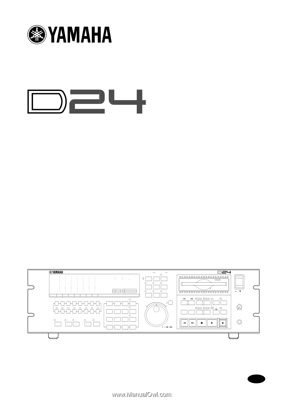
DIGITAL MULTITRACK RECORDER Owner's Manual OVER -dB 0 2 6 10 12 14 20 18 30 20 42 26 60 READY 1 2 3 4 5 RECORD READY SOLO/ SELECT PEAK HOLD AUTO INPUT ALL INPUT MONITOR SELECT OVER 0 -dB 2 6 12 20 30 42 60 READY 0 0 0 0 0 0 0 0 ABS H M S F YAMAHA D24 LOCK WC INT FS 48K BIT 24 - Yamaha D24 | Owner's Manual - Page 2
instructions found in the users manual to eliminate the problem by using one produce satisfactory results, please contact the local retailer authorized to distribute this type of product. If you can not locate the appropriate retailer, please contact Yamaha Corporation of America, Electronic Service - Yamaha D24 | Owner's Manual - Page 3
Laser Diode Properties * Material : AlGaInP * Wavelength : 675-695 nm * Emission Duration : Continuous * Laser Output Power : Less than 44.6 µW (Note) Laser output is measured at a distance of 20 cm from the object lens on the optical pick-up head. CLASS 1 LASER PRODUCT LUOKAN 1 LASERLAITE KLASS 1 - Yamaha D24 | Owner's Manual - Page 4
and may cause a fire. • Turn off audio devices when connecting them to the D24, and use only the cables specified in the relevant owner's manuals. • If you notice any abnormality-such as smoke, odor, or noise-turn off the D24 immediately. Remove the power cord from the AC outlet. Confirm that the - Yamaha D24 | Owner's Manual - Page 5
caused by improper use or operation of the D24. Package Contents The D24 package should contain the following items. Contact your Yamaha dealer if you are missing an item. • D24 Digital Multitrack Recorder • This manual • Power cord • MO disk • Disk eject tool Trademarks ADAT MultiChannel Optical - Yamaha D24 | Owner's Manual - Page 6
Contents iii Contents 1 Welcome to the D24 1 Welcome to the D24 2 About this Manual 3 Installing the D24 3 D24 Features 4 Choosing MO Disks 6 2 Touring the D24 9 Front Panel 10 Display 10 Transport Controls 12 Power Switch & Phones 14 Jog/Data & Shuttle/Cursor Controls 15 Function - Yamaha D24 | Owner's Manual - Page 7
Automatically 65 Recalling Locate Points 66 7 Punch In/Out Recording 67 About Punch In/Out Recording 68 Manual Punch In/Out Rehearsal 69 Manual Punch In/Out Recording 70 Setting the LAST REC IN & OUT Points 71 93 10 Editing Parts 95 Copying Parts 96 Moving Parts 99 D24-Owner's Manual - Yamaha D24 | Owner's Manual - Page 8
the D24 122 Wordclock Connections 123 Dual AES/EBU Recording Time 155 Connecting Disk Drives 156 Assigning SCSI IDs 156 Terminating the SCSI Bus 157 Formatting External Disk Drives 158 Selecting the Work Disk 161 Duplicating MO Disks 162 Copying Projects Between Disk Drives 164 Mounting D24 - Yamaha D24 | Owner's Manual - Page 9
184 Selecting Slot Inputs 184 Installing Cards 185 Using Dual AES/EBU Mode 186 Using the Coaxial Digital Input & Output 187 Assigning the Coaxial Input & Output 188 Emphasis & the D24 188 SCMS & the D24 188 Digital I/O & Wordlength 189 Troubleshooting 191 Appendix 193 Setting the SCSI - Yamaha D24 | Owner's Manual - Page 10
Welcome to the D24 1 Welcome to the D24 1 In this chapter... Welcome to the D24 2 About this Manual 3 Installing the D24 3 D24 Features 4 Choosing MO Disks 6 D24-Owner's Manual - Yamaha D24 | Owner's Manual - Page 11
. The D24's 3U rack size makes it a drop-in alternative to modular digital multitrack recorders. Optional mini YGDAI (Yamaha General Digital Audio Interface) cards offer a variety of analog and digital I/O configurations, with support for all the popular digital audio interconnect formats: AES/EBU - Yamaha D24 | Owner's Manual - Page 12
duplication with two D24s, and the ability to mount D24 MO disks on personal computers. See "D24 Features" on page 4 for a concise rundown of D24 features. About this Manual This Owner's Manual contains all the information you need in order to operate your D24 Digital Multitrack Recorder. Use the - Yamaha D24 | Owner's Manual - Page 13
removable media drives, etc). • Tracks can be expanded by combining up to eight D24s, for a total of 64-tracks. • Continuous recording time can be extended by using two D24s in Serial mode. • 3U rack size for drop-in alternative to tape-based modular digital multitrack recorders. D24-Owner's Manual - Yamaha D24 | Owner's Manual - Page 14
D24 Features 5 Flexible I/O • Optional mini YGDAI (Yamaha General Digital Audio Interface) cards offer a variety of analog and digital I/O configurations, with support for all the popular digital audio interconnect formats: AES/EBU, ADAT, and Tascam TDIF-1. • S/PDIF Coaxial I/O. • Phones. Editing • - Yamaha D24 | Owner's Manual - Page 15
to the D24 Choosing MO Disks The D24's internal MO disk drive uses removable 3.5-inch MO (Magneto Optical) disks for recording and playback. Normal or Overwrite-type MO disks in a variety of sizes can be used, but only 640 MB Overwrite-type disks support 8-track simultaneous recording with a 24 - Yamaha D24 | Owner's Manual - Page 16
. The number of tracks available for simultaneous recording can be expanded using multiple D24s. See "Multiple D24s" on page 144 for more information. The D24's internal MO disk drive supports 230 MB, 540 MB, and 640 MB MO disks. See the Yamaha Professional Audio Web site at the address below - Yamaha D24 | Owner's Manual - Page 17
the D24 9 Touring the D24 2 In this chapter... Front Panel 10 Display 10 Transport Controls 12 Power Switch & Phones 14 Jog/Data & Shuttle/Cursor Controls 15 Function Buttons 16 Peak, Monitor, Format & Chase Buttons 17 Keypad 18 Track Buttons 19 Rear Panel 20 D24-Owner's Manual - Yamaha D24 | Owner's Manual - Page 18
4 5 RECORD READY SOLO/ SELECT PEAK HOLD AUTO INPUT ALL INPUT MONITOR SELECT OVER 0 -dB 2 6 12 20 30 42 60 READY 0 0 0 0 0 0 0 0 ABS H M S F YAMAHA D24 LOCK WC TRACK SELECT EDIT UNDO/ REDO JOG ON DIGITAL MULTITRACK RECORDER PROJECT SEARCH LAST REC IN OUT SET D24-Owner's Manual - Yamaha D24 | Owner's Manual - Page 19
remaining recording time. See "Checking Recording" on page 33 for more information. E Message area The message area consists of two lines that can each display up to 12 characters, which typically show the status and operating mode of the D24 the D24 is master, the D24 uses internal timecode - Yamaha D24 | Owner's Manual - Page 20
12 Chapter 2-Touring the D24 Transport Controls 67 8 PROJECT SEARCH LAST REC 5 IN OUT SET AUTO PUNCH 9 4 J RTN TO ZERO ROLL BACK A B REPEAT REHE AB 3 K ] button selects the top of the next project. See "Searching for Projects" on page 58 for more information. D24-Owner's Manual - Yamaha D24 | Owner's Manual - Page 21
input monitor switching at the punch in and out points, without actually recording anything to disk. The REHE button indicator flashes in Rehearsal Standby mode, and lights up continuously during rehearsal. See "Rehearsing" on page 36, "Manual Punch In/Out Rehearsal" on page 69, and "Auto Punch In - Yamaha D24 | Owner's Manual - Page 22
Rehearse Standby mode. The STOP button indicator lights up when the D24 is stopped. P PLAY button This button is used to start playback, punch out of recording or rehearsal, and in conjunction with the [REC] and [ . 1/4" TRS phone plug Tip (left) Ring (right) Sleeve (ground) D24-Owner's Manual - Yamaha D24 | Owner's Manual - Page 23
the JOG/DATA dial is used to nudge the current position while auditioning a small section of recorded material. See "Nudging the Current Position" on page 53 for more information. When the [ while auditioning the recorded material. See "Shuttling" on page 52 for more information. D24-Owner's Manual - Yamaha D24 | Owner's Manual - Page 24
D24 up when this button is pressed. The D24 must be stopped to use the edit is pressed. The D24 must be stopped to set while the D24 is stopped or during D24 is stopped or during rewind, fast forward, playback, recording which shows how much recording time is available. The The D24 must be stopped to use - Yamaha D24 | Owner's Manual - Page 25
selects the Format function. The FORMAT indicator lights up when the Format function is used. New MO disks and external disk drives must be formatted before they can be used for recording with the D24. See "Formatting MO Disks" on page 26 and "Formatting External Disk Drives" on page 158 for more - Yamaha D24 | Owner's Manual - Page 26
18 Chapter 2-Touring the D24 Keypad 1 7 8 9 PROJECT SELECT 2 4 5 6 LOC MEM RECALL 3 1 2 3 LOC MEM STORE 4 0/- CANCEL ENTER LOCATE 5 67 A Keypad buttons The line of the display. G ENTER button This button is used to select, confirm, and execute functions. D24-Owner's Manual - Yamaha D24 | Owner's Manual - Page 27
continuously. See "Recording" on page 33 for more information. B SOLO/SELECT buttons & indicators 1-8 These buttons are used to solo individual tracks. When a track is soloed, the corresponding SOLO/SELECT indicator lights up. See "Soloing Tracks" on page 48 for more information. D24-Owner's Manual - Yamaha D24 | Owner's Manual - Page 28
D24 DIGITAL MULTITRACK RECORDER TIME CODE OUTPUT INPUT 132 2 1 3 AC IN COAXIAL OUTPUT INPUT SCSI IN SLOT 3 (ANALOG OUT) SLOT 4 (ANALOG OUT) STEREO DIGITAL wordclock signals when the D24 is locked to an external and are used to connect the D24 to other MIDI equipment for use with - Yamaha D24 | Owner's Manual - Page 29
digital audio. See "Using the Coaxial Digital Input & Output" on page 187 for more information. R SLOTs 1-4 These four slots are for use with optional mini YGDAI cards, which offer various analog and digital I/O options. See "Digital Audio I/O" on page 181 for more information. D24-Owner's Manual - Yamaha D24 | Owner's Manual - Page 30
The Basics 23 The Basics 3 In this chapter... Connecting the Power Cord 24 Turning On & Off the D24 24 Write Protecting Disks 24 Inserting & Ejecting Disks 25 Formatting MO Disks 26 Transport Operation Table 27 Indicator Status Tables 28 D24-Owner's Manual - Yamaha D24 | Owner's Manual - Page 31
of the D24, and the plug-end to a suitable stated on the D24 rear panel. AC IN Turning On & Off the D24 To prevent loud clicks D24. Write Protecting Disks MO disks feature write-protect tabs similar to those found on floppy disks, allowing you to protect your recordings - Yamaha D24 | Owner's Manual - Page 32
insert and eject MO disks. 1 Insert the MO disk into the the disk has already been used for recording in the D24, the number and title of the first has been formatted for use with the D24 but not yet used for recording, "01 NO TITLE" is displayed. recording and should not be pressed simultaneously with - Yamaha D24 | Owner's Manual - Page 33
MO Disks New MO disks and MO disks that have been used to store other kinds of data must be formatted before they can be used in the D24. The formatting process prepares a disk for storing D24 D24 disk drive. If the disk is new than the D24, the message set it now. See "Recording" on page 33 for - Yamaha D24 | Owner's Manual - Page 34
no change or invalid Transport Mode Button Stop Play Rew FF Record Rehearse Standby Rehearse Nudge/ A-B Shuttle Repeat [REW] Rew (8x play X REC+PLAY [REC] X to start X X X X X X X recording [REHE] Rehearse Rehearsal standby punch in X X X Cancel X Cancel & X rehearsal - Yamaha D24 | Owner's Manual - Page 35
Transport Indicators q On z Flashing - Off Indicator Stop Transport Mode Play Rew/FF Record Rehearse Standby Rehearse Nudge/ Shuttle REW 8x - - z - - - - set B point has been set Last record or edit operation has not been undone Last record or edit operation has been undone Track - Yamaha D24 | Owner's Manual - Page 36
31 Setting the Recording Resolution 32 Recording 33 Conserving Disk Space 35 Undoing a Recording or Edit 35 Rehearsing 36 Extending the Top of a Project 37 Checking the Time Remaining 38 Metering 39 Using Normal & Fine Metering 40 Using Peak Hold 41 Monitoring 42 D24-Owner's Manual - Yamaha D24 | Owner's Manual - Page 37
Recording About Projects D24 recordings are organized as projects, with a typical project consisting of many sound files and a settings file. Up to 99 projects can be recorded on a single MO or external disk drive. The following settings are stored with each project: recording ) Recording resolution - Yamaha D24 | Owner's Manual - Page 38
Timecode Frame Rate" on page 136 for more information. 5 Set the recording resolution. See "Setting the Recording Resolution" on page 32 for more information. The recording resolution cannot be changed once something is recorded in a project. 6 Proceed to "Recording" on page 33. D24-Owner's Manual - Yamaha D24 | Owner's Manual - Page 39
can easily be transferred to higher-resolution systems, however, the reverse is not true. A 20-bit digital signal recorded on a 16-bit recorder without digital dither will be truncated, resulting in distortion. See "Digital I/O & Wordlength" on page 189 for more information. D24-Owner's Manual - Yamaha D24 | Owner's Manual - Page 40
[RECORD READY] buttons to select tracks for recording. The corresponding READY indicators flash. 5 Set the recording levels in conjunction with the D24 track the [REC] and [PLAY] buttons simultaneously to start recording. Recording starts, "nn RECORDING" appears on the display ("nn" being the project - Yamaha D24 | Owner's Manual - Page 41
the Undo Function. See "Undoing a Recording or Edit" on page 35 for more information. Projects can be titled using the Project Edit Title function. See "Titling Projects" on page 81 for more information. When an untitled project is selected, "NO TITLE" appears on the display. D24-Owner's Manual - Yamaha D24 | Owner's Manual - Page 42
Conserving Disk Space 35 Conserving Disk Space Like all digital audio recorders, the D24 uses up disk space regardless of what's being recorded, so recorded silence uses as much disk space as recorded music. A two minute section of continuous music, for example, will use the same amount of disk - Yamaha D24 | Owner's Manual - Page 43
RECORD READY] buttons to select tracks for recording. The corresponding READY indicators flash. 3 Set the recording levels in conjunction with the D24 track meters. See "Metering" on page 39 for more information. Recording OUT point is set automatically and its indicator lights up. D24-Owner's Manual - Yamaha D24 | Owner's Manual - Page 44
record before the absolute 00:00:00.00 position of a recorded project, if you need to record slip forward the tracks already recorded, and then record the new material. See "Slipping function, the four recorded tracks are slipped forward eight seconds, so that new material can be recorded at the top - Yamaha D24 | Owner's Manual - Page 45
. After repeated recording and editing, there may be a lot of unused sound files on the disk. To delete these unused sound files and recover the disk space for further recording or editing, use the Optimize function. See "Recovering Disk Space" on page 172 for more information. D24-Owner's Manual - Yamaha D24 | Owner's Manual - Page 46
. Okay Back off recording level OVER -dB 0 2 6 12 20 30 42 60 READY OVER 0 -dB 2 6 12 20 30 42 60 READY L R When the Shuttle, Nudge, Time Compression, or Pitch Change function is used, track meters 7 and 8 function as stereo meters, and meters 1 through 6 are turned off. D24-Owner's Manual - Yamaha D24 | Owner's Manual - Page 47
18 20 42 60 26 READY L R Fine mode is useful for accurate level setting when recording reference tones at -10, -14, -18, or -20 dB, but can also be used for precise metering with normal . 5 Press the [UTILITY] button again to leave utility. The UTILITY indicator goes out. D24-Owner's Manual - Yamaha D24 | Owner's Manual - Page 48
: On OVER -dB 0 2 6 12 20 30 42 60 READY OVER 0 -dB 2 6 12 20 30 42 60 READY L R OVER 0 -dB 2 6 12 20 30 42 60 READY L R D24-Owner's Manual - Yamaha D24 | Owner's Manual - Page 49
42 Chapter 4-Recording Monitoring In a typical D24 multitrack recording system, monitoring is performed at the mixing console via the tape returns, which are connected to the D24's track outputs via mini YGDAI cards ("About mini YGDAI Cards" on page 182). The signal source for each track output, - Yamaha D24 | Owner's Manual - Page 50
, which has priority over all other settings, is turned on and the track outputs output the track input signals regardless of the transport mode and [RECORD READY] button. All Input is useful when you want to monitor track inputs regardless of any other settings. AUTO INPUT ALL INPUT Stop/FF/Rew - Yamaha D24 | Owner's Manual - Page 51
Setting the Roll-back Time 50 Using Virtual Tracks 51 Shuttling 52 Nudging the Current Position 53 Setting the Nudge Time 54 Using Varispeed 55 D24-Owner's Manual - Yamaha D24 | Owner's Manual - Page 52
back recorded material. 1 While the D24 is stopped is pressed and held during playback, the D24 rewinds (8x) or fast forwards ( recording and rehearsal, the [PLAY] button is used to punch in and out of recording pressed during fast forward or rewind, the D24 stops, and then starts playback. Pressing - Yamaha D24 | Owner's Manual - Page 53
must first set the A and B points, which can be set while the D24 is stopped or during rewind, fast forward, playback, recording, or rehearsal, but cannot be changed during A-B repeat playback. 1 While holding A. The A and B points for each project are saved to disk automatically. D24-Owner's Manual - Yamaha D24 | Owner's Manual - Page 54
tracks mixed to the left channel, and even numbered tracks mixed to the right channel. The COAXIAL DIGITAL STEREO OUTPUT and track outputs are not affected by the Solo function. When Solo Out is set output 1 outputs the track 1 signal, while track outputs 2 through 8 are muted. D24-Owner's Manual - Yamaha D24 | Owner's Manual - Page 55
, press the [RTN TO ZERO] button. If the current project doesn't have a zero position, the Return to Zero function locates the top of the project. D24-Owner's Manual - Yamaha D24 | Owner's Manual - Page 56
roll back by the specified amount. If the [ROLL BACK] button is pressed during playback, the D24 rolls back by the specified amount, and then continues playing. Current position Roll-back Roll-back time [UTILITY] button again to leave utility. The UTILITY indicator goes out. D24-Owner's Manual - Yamaha D24 | Owner's Manual - Page 57
4-1 5 5-1 6 6-1 7 7-1 8 8-1 64 virtual tracks 1-1 1-2 1-3 1-4 1-5 1-6 1-7 1-8 2-1 2-2 2-3 1 While the D24 is stopped, press the [V. TRACK SELECT] button. The V. TRACK SELECT indicator lights up and the display Selected main track TRK 1234567 8 VI R 11511111 Assigned virtual track D24-Owner's Manual - Yamaha D24 | Owner's Manual - Page 58
to shuttle forwards or backwards at various speeds while listening to the recorded material. 1 Press the [JOG ON] button. The JOG ON (see "Assigning the Coaxial Input & Output" on page 188), the COAXIAL STEREO DIGITAL OUTPUT. Track outputs 1 through 6 do not output anything when these functions are - Yamaha D24 | Owner's Manual - Page 59
a small section of the recorded material after the current position. OUT points for auto punch in/out recording. The length of the section to be and the position, including sub-frame digits, appears on the 2nd line. The DIGITAL OUTPUT. Track outputs 1 through 6 do not output anything - Yamaha D24 | Owner's Manual - Page 60
your selection, or the [CANCEL] button to cancel the Nudge Time function. 5 Press the [UTILITY] button again to leave utility. The UTILITY indicator goes out. D24-Owner's Manual - Yamaha D24 | Owner's Manual - Page 61
the pitch. Varispeed can be set while the D24 is stopped or during playback, recording, or rehearsal. 1 Press the [VARI SPEED] trouble synchronizing to the D24's wordclock at certain varispeed settings. When the D24 is used as a wordclock slave, the Varispeed function cannot be used because the D24 - Yamaha D24 | Owner's Manual - Page 62
Locating the LAST REC IN & OUT Points 62 Locating Positions Directly 63 Storing Locate Points 64 Storing Locate Points Automatically 65 Recalling Locate Points 66 D24-Owner's Manual - Yamaha D24 | Owner's Manual - Page 63
If the [ ] PROJECT SEARCH button is pressed while the last recorded project is selected, "nn NEW PROJ" appears on the display. See "Recording" on page 33 for more information. Project Search Confirmation the [UTILITY] button again to leave utility. The UTILITY indicator goes out. D24-Owner's Manual - Yamaha D24 | Owner's Manual - Page 64
SELECT indicator goes out. In the following example, project number 4 is selected. Current position 01 PROJECT 02 PROJECT 03 PROJECT 04 PROJECT PROJECT SELECT 4 ENTER D24-Owner's Manual - Yamaha D24 | Owner's Manual - Page 65
, for example, the project starts at the absolute time of 01:00:00.00, the Return to Zero function locates the top of the project. D24-Owner's Manual - Yamaha D24 | Owner's Manual - Page 66
the A & B Points The A and B points can be set while the D24 is stopped or during rewind, fast forward, playback, recording, or rehearsal. 1 While holding down the [SET] button, press the [A] is pressed during playback, the stored point is located, and then playback continues. D24-Owner's Manual - Yamaha D24 | Owner's Manual - Page 67
The LAST REC IN and OUT points are typically used to mark the punch-in and punch-out points for recording and rehearsal, but can also be used as general locate points. 1 While holding down the [SET] button during playback, the stored point is located, and then playback continues. D24-Owner's Manual - Yamaha D24 | Owner's Manual - Page 68
position is located. In the following example, the position 00:03:00 is located. 00:00:00 Current position 00:03:00 3 0/- ENTER LOCATE x2 D24-Owner's Manual - Yamaha D24 | Owner's Manual - Page 69
project using the Locate Memory Store function. Locate points can be stored while the D24 is stopped or during rewind, fast forward, playback, recording, or rehearsal. 1 Display the position that you want to store on the 01:00.00.0 CAPTURE LOC MEM STORE 5 ENTER LOC MEM STORE D24-Owner's Manual - Yamaha D24 | Owner's Manual - Page 70
Repeat step 3 to store further locate points. Locate points can be stored while the D24 is stopped or during rewind, fast forward, playback, recording, or rehearsal. 5 Press the [LOC MEM STORE] button to leave the Locate ENTER LOC MEM STORE LOC MEM: 01 LOC MEM: 02 LOC MEM: 03 D24-Owner's Manual - Yamaha D24 | Owner's Manual - Page 71
, locate memory number 5 is recalled and located. 00:00:00.00 Current position 00:01:00.00 LOC MEM RECALL 5 ENTER LOCATE LOC MEM RECALL D24-Owner's Manual - Yamaha D24 | Owner's Manual - Page 72
chapter... About Punch In/Out Recording 68 Manual Punch In/Out Rehearsal 69 Manual Punch In/Out Recording 70 Setting the LAST REC IN & OUT Points 71 Auto Punch In/Out Rehearsal 72 Auto Punch In/Out Recording 73 Setting the Pre-roll Time 76 Setting the Post-roll Time 76 D24-Owner's Manual - Yamaha D24 | Owner's Manual - Page 73
Fix Take function. Punch In/Out Fade In/Out When dissimilar sounds are digitally spliced together, the discontinuity and sudden level change sometimes produces an audible click. To smooth the transition when using punch in/out recording, a small fade in/out is applied at the punch-in and out points - Yamaha D24 | Owner's Manual - Page 74
illustration shows the procedure for manual punch-in/out rehearsal. 1-1 1 READY 2 2-1 2 3-1 3 4-1 4 5-1 5 6-1 6 7-1 7 8-1 8 2 RECORD READY LAST REC IN indicator lights up. 4 Press the [PLAY] button to punch out. The D24 stops rehearsal and continues with normal playback. The LAST REC OUT point is - Yamaha D24 | Owner's Manual - Page 75
shows the procedure for manual punch-in/out recording. 1-1 1 READY 2 2-1 2 3-1 3 4-1 4 5-1 5 6-1 6 7-1 7 8-1 8 2 RECORD READY PLAY LAST REC lights up. 4 Press the [PLAY] button to punch out. The D24 stops recording and continues with normal playback. The REC button indicator goes out and - Yamaha D24 | Owner's Manual - Page 76
REC IN and OUT points are set automatically when you manually punch in and out of recording or rehearsal. They can also be set using the [SET] LAST REC [IN] and [OUT] buttons while the D24 is stopped or during rewind, fast forward, playback, recording, or rehearsal. When the LAST REC IN or OUT - Yamaha D24 | Owner's Manual - Page 77
recording without actually recording 7-1 7 8-1 8 Locate Play Rehearse Play Locate 2 RECORD READY AUTO PUNCH REHE PLAY 1 Set the LAST REC . 2 Use the [RECORD READY] buttons to select tracks for recording. The corresponding READY indicators D24 waits. 7 Press the [AUTO PUNCH] - Yamaha D24 | Owner's Manual - Page 78
IN & OUT Points" on page 71 for more information. 2 Use the [RECORD READY] buttons to select tracks for recording. The corresponding READY indicators flash. 3 Press the [AUTO PUNCH] button. The Pre-roll point is located, and the D24 waits. The display shows "AUTO PUNCH-REC TAKE 2". D24-Owner's Manual - Yamaha D24 | Owner's Manual - Page 79
display ("nn" being the number of the take to be auditioned). Take 0 is the original material and can be auditioned even before any takes are recorded. D24-Owner's Manual - Yamaha D24 | Owner's Manual - Page 80
Auto Punch In/Out Recording 75 9 Use the JOG/DATA dial to select the take that you want to audition, and then press the [ENTER] button. The D24 plays the selected take along with the seven other main tracks you press the [CANCEL] button, repeat step 14 to select another take. D24-Owner's Manual - Yamaha D24 | Owner's Manual - Page 81
76 Chapter 7-Punch In/Out Recording Setting the Pre-roll Time The pre-roll time can be set from 1 to 30 seconds, the default being 5 seconds. [CANCEL] button to cancel the Post Roll function. 5 Press the [UTILITY] button again to leave utility. The UTILITY indicator goes out. D24-Owner's Manual - Yamaha D24 | Owner's Manual - Page 82
Editing Projects 77 Editing Projects 8 In this chapter... Copying Projects 78 Erasing Projects 79 Deleting Projects 80 Titling Projects 81 Protecting Projects 82 Modifying a Project's Start Time 83 D24-Owner's Manual - Yamaha D24 | Owner's Manual - Page 83
the following example, project 2 is copied with new project number 4. 01 PROJECT 02 PROJECT 03 PROJECT Copied 01 PROJECT 02 PROJECT 03 PROJECT 04 PROJECT D24-Owner's Manual - Yamaha D24 | Owner's Manual - Page 84
PROJECT 03 PROJECT 04 PROJECT Contents erased 01 PROJECT 02 PROJECT 03 PROJECT 04 PROJECT When a project's contents are erased, the time available for additional recording is increased. D24-Owner's Manual - Yamaha D24 | Owner's Manual - Page 85
. 01 PROJECT 02 PROJECT 03 PROJECT 04 PROJECT Deleted 01 PROJECT 03 PROJECT 04 PROJECT When a project's contents are deleted, the time available for additional recording is increased. D24-Owner's Manual - Yamaha D24 | Owner's Manual - Page 86
SURE" appears on the display. 7 Press the [ENTER] button to set the title. 8 Press the [EDIT] button to leave edit. The EDIT indicator goes out. D24-Owner's Manual - Yamaha D24 | Owner's Manual - Page 87
selected, "UNPROTECTED" appears on the display, and when ON is selected, "PROTECTED" appears. 8 Press the [EDIT] button to leave edit. The EDIT indicator goes out. D24-Owner's Manual - Yamaha D24 | Owner's Manual - Page 88
TC Modify function is used to modify a project's start time, which is initially set when a project is first recorded. See "Recording" on page 33 for more information. 1 Select the project whose start time you want to modify. 2 Press modified to 00:10:00.00 01 PROJECT 00:15:00.00 D24-Owner's Manual - Yamaha D24 | Owner's Manual - Page 89
Editing Tracks 85 Editing Tracks 9 In this chapter... Copying Tracks 86 Moving Tracks 88 Erasing Tracks 90 Swapping Tracks 91 Slipping Tracks 93 D24-Owner's Manual - Yamaha D24 | Owner's Manual - Page 90
the copy operation is complete, "FINISHED" appears on the display and the UNDO/REDO indicator lights up, indicating that it can be undone. See "Undoing a Recording or Edit" on page 35 for more information. To copy another track, press the [ENTER] button to return to step - Yamaha D24 | Owner's Manual - Page 91
Copy From: ALL To: V_TR 1 Main tracks 1 2 3 4 5 6 7 8 Tracks 1 and 2 copied to virtual tracks 1-3 and 2-3 Virtual tracks 1-3 2-3 3-3 4-3 5-3 6-3 7-3 8-3 Tracks 1 through 8 copied to virtual tracks 1-1, 2-1, 3-1, etc. Virtual tracks 1-1 2-1 3-1 4-1 5-1 6-1 7-1 8-1 D24-Owner's Manual - Yamaha D24 | Owner's Manual - Page 92
the move operation is complete, "FINISHED" appears on the display and the UNDO/REDO indicator lights up, indicating that it can be undone. See "Undoing a Recording or Edit" on page 35 for more information. To move another track, press the [ENTER] button to return to step - Yamaha D24 | Owner's Manual - Page 93
Move From: ALL To: V_TR 1 Main tracks 1 2 3 4 5 6 7 8 Tracks 1 and 2 moved to virtual tracks 1-3 and 2-3 Virtual tracks 1-3 2-3 3-3 4-3 5-3 6-3 7-3 8-3 Tracks 1 through 8 moved to virtual tracks 1-1, 2-1, 3-1, etc. Virtual tracks 1-1 2-1 3-1 4-1 5-1 6-1 7-1 8-1 D24-Owner's Manual - Yamaha D24 | Owner's Manual - Page 94
REDO indicator lights up, indicating that it can be undone. See "Undoing a Recording or Edit" on page 35 for more information. To erase another track, press les, taking up disk space, and reducing the time remaining for additional recording. To delete these unused files and recover the disk space, use - Yamaha D24 | Owner's Manual - Page 95
the swap operation is complete, "FINISHED" appears on the display and the UNDO/REDO indicator lights up, indicating that it can be undone. See "Undoing a Recording or Edit" on page 35 for more information. To swap other tracks, press the [ENTER] button to return to step - Yamaha D24 | Owner's Manual - Page 96
Swap From: ALL To: V_TR 1 Main tracks 1 2 3 4 5 6 7 8 Tracks 1 and 2 swapped with virtual tracks 1-3 and 2-3 Virtual tracks 1-3 2-3 3-3 4-3 5-3 6-3 7-3 8-3 Tracks 1 through 8 swapped with virtual tracks 1-1, 2-1, 3-1, etc. Virtual tracks 1-1 2-1 3-1 4-1 5-1 6-1 7-1 8-1 D24-Owner's Manual - Yamaha D24 | Owner's Manual - Page 97
the slip operation is complete, "FINISHED" appears on the display and the UNDO/REDO indicator lights up, indicating that it can be undone. See "Undoing a Recording or Edit" on page 35 for more information. To slip another track, press the [ENTER] button to return to step - Yamaha D24 | Owner's Manual - Page 98
94 Chapter 9-Editing Tracks 10 Press the [EDIT] button to leave edit. The EDIT indicator goes out. In the following example, track 2 is slipped to a new start time. Project start time 00:00:00.00 1 2 Track Slip 3 TR: 2 4 5 6 7 8 Track slipped to 00:00:30.00 D24-Owner's Manual - Yamaha D24 | Owner's Manual - Page 99
Editing Parts 95 Editing Parts 10 In this chapter... Copying Parts 96 Moving Parts 99 Deleting Parts 102 Erasing Parts 104 Inserting Parts 106 Insert Copying Parts 108 Time Compression 111 Pitch Change 116 D24-Owner's Manual - Yamaha D24 | Owner's Manual - Page 100
end position, and then press the [ENTER] button. "COPY TR nn-TO TR nn" appears on the display ("TO TR nn" being the destination track). D24-Owner's Manual - Yamaha D24 | Owner's Manual - Page 101
track. 18 Press the [ENTER] button. "EDIT COPY-ARE YOU SURE" appears on the display. If the destination track contains material, "OVER WRITE" appears instead. D24-Owner's Manual - Yamaha D24 | Owner's Manual - Page 102
appears on the display and the UNDO/REDO indicator lights up, indicating that it can be undone. See "Undoing a Recording or Edit" on page 35 for more information. To copy another part, press the [ENTER] button to return to step .00 Copy x1 Copy x2 To TR: 3 TO point 00:00:40.00 D24-Owner's Manual - Yamaha D24 | Owner's Manual - Page 103
end position, and then press the [ENTER] button. "MOVE TR nn-TO TR nn" appears on the display ("TO TR nn" being the destination track). D24-Owner's Manual - Yamaha D24 | Owner's Manual - Page 104
track. 18 Press the [ENTER] button. "EDIT MOVE-ARE YOU SURE" appears on the display. If the destination track contains material, "OVER WRITE" appears instead. D24-Owner's Manual - Yamaha D24 | Owner's Manual - Page 105
appears on the display and the UNDO/REDO indicator lights up, indicating that it can be undone. See "Undoing a Recording or Edit" on page 35 for more information. To move another part, press the [ENTER] button to return to step .00 Move x1 Move x2 To TR: 3 TO point 00:00:40.00 D24-Owner's Manual - Yamaha D24 | Owner's Manual - Page 106
JOG/DATA dial or keypad to adjust the end position, and then press the [ENTER] button. "EDIT DELETE-ARE YOU SURE" appears on the display. D24-Owner's Manual - Yamaha D24 | Owner's Manual - Page 107
indicator lights up, indicating that it can be undone. See "Undoing a Recording or Edit" on page 35 for more information. To delete another part, taking up disk space, and reducing the time remaining for additional recording. To delete these unused files and recover the disk space, use the - Yamaha D24 | Owner's Manual - Page 108
JOG/DATA dial or keypad to adjust the end position, and then press the [ENTER] button. "EDIT ERASE-ARE YOU SURE" appears on the display. D24-Owner's Manual - Yamaha D24 | Owner's Manual - Page 109
indicator lights up, indicating that it can be undone. See "Undoing a Recording or Edit" on page 35 for more information. To erase another part, taking up disk space, and reducing the time remaining for additional recording. To delete these unused files and recover the disk space, use the - Yamaha D24 | Owner's Manual - Page 110
JOG/DATA dial or keypad to adjust the end position, and then press the [ENTER] button. "EDIT INSR S-ARE YOU SURE" appears on the display. D24-Owner's Manual - Yamaha D24 | Owner's Manual - Page 111
on the display and the UNDO/REDO indicator lights up, indicating that it can be undone. See "Undoing a Recording or Edit" on page 35 for more information. To insert a part into another track, press the [ENTER 15.00 TR 2: After Empty part inserted Existing material moved backward D24-Owner's Manual - Yamaha D24 | Owner's Manual - Page 112
end position, and then press the [ENTER] button. "INSR TR nn-TO TR nn" appears on the display ("TO TR nn" being the destination track). D24-Owner's Manual - Yamaha D24 | Owner's Manual - Page 113
. If the destination contains material that will be overwritten when the existing material on the track is moved backward, "OVER WRITE" appears on the display. D24-Owner's Manual - Yamaha D24 | Owner's Manual - Page 114
on the display and the UNDO/REDO indicator lights up, indicating that it can be undone. See "Undoing a Recording or Edit" on page 35 for more information. To insert a copied part into another track, press the [ENTER TR3 Existing material moved backward TO point 00:00:40.00 D24-Owner's Manual - Yamaha D24 | Owner's Manual - Page 115
is used to stretch or squeeze recorded material without affecting its pitch. material is stretched or squeezed and the result is recorded to the specified virtual track, from which it mode is used to perform the actual time compression and record the result to a virtual track. When auditioning a - Yamaha D24 | Owner's Manual - Page 116
assigned to tracks 7 and 8 (see "Assigning the Coaxial Input & Output" on page 188), the COAXIAL STEREO DIGITAL OUTPUT. Track outputs 1 through 6 do not output anything when these functions are used. 14 Press the [ENTER] , and from here you can select either "TEST PLAY" or "REC." D24-Owner's Manual - Yamaha D24 | Owner's Manual - Page 117
message "TOO SHORT" appears. "TIME COMP-TO V_TR nn" appears on the display ("nn" being the virtual track to which the processed material will be recorded). D24-Owner's Manual - Yamaha D24 | Owner's Manual - Page 118
display and the UNDO/REDO indicator lights up, indicating that it can be undone. See "Undoing a Recording or Edit" on page 35 for more information. To stretch or squeeze another part, press the is squeezed by 88.23% and recorded to virtual track 2-1 at the TO point with its new D24-Owner's Manual - Yamaha D24 | Owner's Manual - Page 119
00:01:00.00 00:01:30.00 When a part is stretched or squeezed, any stored locate points will be out of sync with the recorded material. D24-Owner's Manual - Yamaha D24 | Owner's Manual - Page 120
track with the specified pitch change, while Rec mode is used to perform the actual pitch change and record the result to a virtual track. Test Play Mode 7 Having selected "TEST PLAY," press the [ENTER] button track, assign it to a main track first, and then pitch the main track. D24-Owner's Manual - Yamaha D24 | Owner's Manual - Page 121
assigned to tracks 7 and 8 (see "Assigning the Coaxial Input & Output" on page 188), the COAXIAL STEREO DIGITAL OUTPUT. Track outputs 1 through 6 do not output anything when these functions are used. 14 Press the [ENTER] . ST point 00:01:00.00 From TR: 2 ENTER Audition ENTER D24-Owner's Manual - Yamaha D24 | Owner's Manual - Page 122
nn" being the virtual track to which the pitched material will be recorded). 25 Use the JOG/DATA dial to select the destination virtual track V. TR 3 Examples Result Pitched part of TR 1 recorded to V. TR 1-3 Pitched parts of TR 1/2 recorded to V. TR 1-3/2-3 All the existing data in the - Yamaha D24 | Owner's Manual - Page 123
to cancel. If you press the [ENTER] button, the selected material is pitched and the result is recorded to the specified virtual track. Use the Virtual Track function to assign the virtual track to a main any stored locate points will be out of sync with the recorded material. D24-Owner's Manual - Yamaha D24 | Owner's Manual - Page 124
Wordclocks 121 Wordclocks 11 In this chapter... Wordclocks & the D24 122 Wordclock Connections 123 Dual AES/EBU Mode 123 Selecting a Wordclock Source 124 Wordclock System Examples 126 Terminating BNC Wordclock Distribution 131 D24-Owner's Manual - Yamaha D24 | Owner's Manual - Page 125
certain applications, however, such as recording a digital source via the COAXIAL STEREO DIGITAL INPUT, the D24 must be configured as a wordclock slave. Wordclock signals can be distributed via dedicated cables, typically BNC cables, or derived from digital audio connections, which are synchronous - Yamaha D24 | Owner's Manual - Page 126
recording resolution is selected, lower the volume of your monitoring system just in case your digital mixer, or another device locked to the D24's wordclock, becomes unlocked and produces SLOT 1, SLOT 2, REMOTE IN, or COAXIAL IN. Dual AES/EBU Mode When using the higher sampling rates of 88.2 kHz - Yamaha D24 | Owner's Manual - Page 127
new project is created. Once something has been recorded in a project, the sampling rate cannot be changed DIGITAL INPUT (41.454 kHz-50.88 kHz). Internal 44.1 kHz wordclock, 88.2 kHz sampling rate, and Dual AES/EBU mode. Internal 48 kHz wordclock, 96 kHz sampling rate, and Dual AES D24-Owner's Manual - Yamaha D24 | Owner's Manual - Page 128
sampling rate will be the same for each device. So if the D24 is wordclock master and is running at 48 kHz, when you mix down to DAT, for example, via a digital connection from the mixing console, the DAT recording will also be at 48 kHz. If you intend to burn your own - Yamaha D24 | Owner's Manual - Page 129
digital audio is transferred between the D24 and digital mixing console, and from the digital mixing console to the DAT deck, providing multitrack recording, mixing, and mixdown recording to DAT. The D24 is the wordclock master and the digital 01V (wordclock slave) mYGDAI AES/EBU PAD 26dB 26dB - Yamaha D24 | Owner's Manual - Page 130
MULTITRACK RECORDER PROJECT SEARCH LAST REC IN OUT SET AUTO PUNCH RTN TO ZERO ROLL BACK A B REPEAT REHE AB REW FF STOP PLAY REC JOG/DATA SHUTTLE/ CURSOR POWER ON OFF 0 10 PHONES LEVEL PHONES Wordclock source: INT Sync cable D24-B (wordclock slave) REMOTE IN/ SYNC IN OVER - Yamaha D24 | Owner's Manual - Page 131
Multitrack) recorders and a digital mixing console. D24-A is the wordclock master, and D24-B, the MDMs, and the digital mixing console are wordclock slaves. Since the timecode source on D24-B is set to REMOTE IN, the wordclock signal is transmitted from D24-A to D24-B via the 15-pin sync cable. D24 - Yamaha D24 | Owner's Manual - Page 132
RECORD READY SOLO/ SELECT PEAK HOLD AUTO INPUT ALL INPUT MONITOR SELECT OVER 0 -dB 2 6 12 20 30 42 60 READY 0 0 0 0 0 0 0 0 ABS H M S F YAMAHA D24 EDIT UNDO/ REDO JOG ON DIGITAL MULTITRACK RECORDER PROJECT SEARCH LAST REC IN Digital Out Wordclock source: Internal D24-Owner's Manual - Yamaha D24 | Owner's Manual - Page 133
MULTITRACK RECORDER PROJECT SEARCH LAST REC IN OUT SET AUTO PUNCH RTN TO ZERO ROLL BACK A B REPEAT REHE AB REW FF STOP PLAY REC JOG/DATA SHUTTLE/ CURSOR POWER ON OFF 0 10 PHONES LEVEL PHONES Wordclock source: INT Sync cable D24-B (wordclock slave) REMOTE IN/ SYNC IN - Yamaha D24 | Owner's Manual - Page 134
cables, it must be terminated correctly. Termination is typically applied at the last device, although it depends on the distribution method being used. The D24's WORD CLOCK 75Ω TERM/THRU switch allows the D24 Wordclock slave WC IN (BNC) Device-C Termination = ON Wordclock slave D24-Owner's Manual - Yamaha D24 | Owner's Manual - Page 135
In this chapter... Timecode & the D24 134 Timecode Connections 134 Selecting a Timecode Source 135 Setting the Timecode Frame Rate 136 Setting a Timecode Offset 137 Chasing External Timecode 138 Setting the Chase Speed 139 Transmitting MTC 139 Timecode Hookup Examples 140 D24-Owner's Manual - Yamaha D24 | Owner's Manual - Page 136
& the D24 The D24 supports longitudinal timecode playback, recording, or rehearsal. Timecode Connections When the timecode source is set to TIME CODE IN, the D24 synchronizes to connector transmits internally generated SMPTE/EBU timecode when the D24 is used as the timecode master, or the timecode - Yamaha D24 | Owner's Manual - Page 137
the D24 is synchronized D24 to external timecode. External MTC timecode via the MIDI IN port. Used when synchronizing the D24 D24s to the timecode from the master D24 synchronizing the D24 to external Used when synchronizing the D24 to external timecode and up) and the D24 is automatically configured - Yamaha D24 | Owner's Manual - Page 138
setup. The SETUP indicator goes out. The frame rate you choose will ultimately depend on your application and recording system. In general, 24 fps is used for film work, 25 fps is used with European them and agree on a timecode frame rate before you start recording on the D24. D24-Owner's Manual - Yamaha D24 | Owner's Manual - Page 139
timecode value of 01:00:00.00.0 (1 hour) will correspond to 01:05:00.00.0 (1 hour and 5 minutes) on the D24. 1 Press the [SETUP] button. The SETUP indicator lights up. 2 Use the JOG/DATA dial to select "TC OFFSET," and then :01:00.00 offset +00:01:00.00 offset Project Project D24-Owner's Manual - Yamaha D24 | Owner's Manual - Page 140
D24s in a multiple-unit system, or to synchronize a single D24 to an external timecode source. The D24 the D24 first the D24 chases and synchronizes D24 will now D24 automatically starts playback, and when the incoming timecode stops, the D24 D24s" on page 144 for details about using multiple D24s - Yamaha D24 | Owner's Manual - Page 141
D24's wordclock, such as digital mixers, may become unlocked and produces unpleasant noises. In this case, you should reduce the D24's Chase Speed. At slower Chase Speeds, however, the D24 source. The D24 transmits MTC during rewind, fast forward, playback, recording, or rehearsal. D24-Owner's Manual - Yamaha D24 | Owner's Manual - Page 142
the digital mixing console as MTC. D24-A (WC master, TC master) SYNC OUT OVER -dB 0 2 6 10 12 14 20 18 30 20 42 26 60 READY 1 2 3 4 5 RECORD READY SOLO/ SELECT PEAK HOLD AUTO INPUT ALL INPUT MONITOR SELECT OVER 0 -dB 2 6 12 20 30 42 60 READY 0 0 0 0 0 0 0 0 ABS H M S F YAMAHA D24 - Yamaha D24 | Owner's Manual - Page 143
3 4 5 RECORD READY SOLO/ SELECT PEAK HOLD AUTO INPUT ALL INPUT MONITOR SELECT OVER 0 -dB 2 6 12 20 30 42 60 READY 0 0 0 0 0 0 0 0 ABS H M S F YAMAHA D24 LOCK WC INT V. TRACK SELECT EDIT UNDO/ REDO JOG ON DIGITAL MULTITRACK RECORDER PROJECT SEARCH LAST REC IN OUT SET AUTO - Yamaha D24 | Owner's Manual - Page 144
& Video Sync 13 In this chapter... Multiple D24s 144 Expanding the Number of Tracks 145 Extending the Recording Time 147 Setting the Serial Point 149 Using Video Sync 149 Terminating BNC Video Sync Distribution 150 Connecting a Video Editor 151 Video Hookup Example 151 D24-Owner's Manual - Yamaha D24 | Owner's Manual - Page 145
MULTITRACK RECORDER PROJECT SEARCH LAST REC IN OUT SET AUTO PUNCH RTN TO ZERO ROLL BACK A B REPEAT REHE AB REW FF STOP PLAY REC JOG/DATA SHUTTLE/ CURSOR POWER ON OFF 0 10 PHONES LEVEL PHONES TC: REMOTE IN/30 fps Chase: On Remote ID: 4 SYNC OUT Next D24 D24-Owner's Manual - Yamaha D24 | Owner's Manual - Page 146
MULTITRACK RECORDER PROJECT SEARCH LAST REC IN OUT SET AUTO PUNCH RTN TO ZERO ROLL BACK A B REPEAT REHE AB REW FF STOP PLAY REC JOG/DATA SHUTTLE/ CURSOR TC: REMOTE IN/30 fps Chase: On, Remote ID: 3 POWER ON OFF 0 10 PHONES LEVEL PHONES 15-pin sync cable D24-D (WC slave - Yamaha D24 | Owner's Manual - Page 147
Shuttle, Virtual Track, Solo, Peak Hold, Record Ready, Auto Input, All Input, Format, Chase on/off, Remain, ABS/REL, Undo/Redo, edit functions, utility functions, and setup functions. These functions must be set on each slave D24 individually before turning on the Chase function. D24-Owner's Manual - Yamaha D24 | Owner's Manual - Page 148
cable. D24-A (WC master, TC master) SYNC OUT OVER -dB 0 2 6 10 12 14 20 18 30 20 42 26 60 READY 1 2 3 4 5 RECORD READY SOLO/ SELECT PEAK HOLD AUTO INPUT ALL INPUT MONITOR SELECT OVER 0 -dB 2 6 12 20 30 42 60 READY 0 0 0 0 0 0 0 0 ABS H M S F YAMAHA D24 DIGITAL MULTITRACK RECORDER - Yamaha D24 | Owner's Manual - Page 149
the slave D24 should be and the D24 is automatically slave D24 an exclusive D24. Operation 1 Recording or playback is started in the normal way on the master D24. The slave D24 D24s during playback, a task that can be automated using the automix functions of a digital mixing console. 4 The slave D24 - Yamaha D24 | Owner's Manual - Page 150
Serial Point function determines the position at which the slave D24 starts recording or playback, when two D24s are used to extend the continuous recording time. The serial point can be entered using the keypad BNC Video Sync Distribution" on page 150 for hookup examples. D24-Owner's Manual - Yamaha D24 | Owner's Manual - Page 151
cables, it must be terminated correctly. Normally, termination is applied at the last device connected, although it depends on the distribution method being used. The D24's VIDEO 75Ω ON/OFF switch allows the D24 sync slave VIDEO IN (BNC) Device-C Termination = ON Video sync slave D24-Owner's Manual - Yamaha D24 | Owner's Manual - Page 152
Hookup Example In the following example, the D24 provides multitrack recording and playback in a video editing system. The D24 and VTRs are controlled by the video editor using 9-pin protocols. Note that not all video editors are supported. The D24's timecode source is set to SERIAL and timecode - Yamaha D24 | Owner's Manual - Page 153
... SCSI & the D24 154 Using External Disk Drives 154 Certified Disk Drives 155 Available Recording Time 155 Connecting Disk MO Disks 162 Copying Projects Between Disk Drives 164 Mounting D24 Disks on a Personal Computer 165 Connecting the D24 to a Personal Computer 166 D24-Owner's Manual - Yamaha D24 | Owner's Manual - Page 154
D24 Additional recording space can be made available by connecting optional, external SCSI hard disk drives or removable media drives to the D24's SCSI port. The SCSI interface supports Narrow SCSI-2 (FAST-20). The D24's filing system supports projects to the internal MO disk drive using the Backup - Yamaha D24 | Owner's Manual - Page 155
Yamaha and are certified for use with the D24. Other disk drives may work just as well, although performance cannot be guaranteed. The D24's SCSI interface supports digital audio (e.g., 188 × 6 = 1,128). Disk Capacity 1 GB 2 GB 4.5 GB 6.5 GB 9.1 GB1 Recording 1. The D24's filing system supports up to - Yamaha D24 | Owner's Manual - Page 156
MULTITRACK RECORDER PROJECT SEARCH LAST REC IN OUT SET AUTO PUNCH RTN TO ZERO ROLL BACK A B REPEAT REHE AB REW FF STOP PLAY REC JOG/DATA SHUTTLE/ CURSOR POWER ON OFF 0 10 PHONES LEVEL PHONES External SCSI disk drive SCSI cable SCSI port SCSI port SCSI ID settings D24 - Yamaha D24 | Owner's Manual - Page 157
manually RECORD READY SOLO/ SELECT PEAK HOLD AUTO INPUT ALL INPUT MONITOR SELECT OVER 0 -dB 2 6 12 20 30 42 60 READY 0 0 0 0 0 0 0 0 ABS H M S F YAMAHA D24 ON DIGITAL MULTITRACK RECORDER cable SCSI cable SCSI port SCSI port SCSI port SCSI port SCSI ID settings D24 internal: 6 D24 MO - Yamaha D24 | Owner's Manual - Page 158
with the D24. The formatting process prepares a disk for storing D24 data. use the maximum capacity supported by the D24, which is 8.4 GB the external hard disk drive to the D24. 2 Select the external hard disk drive 00:00.00," set it now. See "Recording" on page 33 for more information. Otherwise - Yamaha D24 | Owner's Manual - Page 159
'll only be able to use 2 GB for recording on the D24. 1 Connect the external hard disk drive to a D24 does not support FAT32 volumes, so be sure to format as FAT16. 2 Connect the external hard disk drive to the D24 :00:00.00," set it now. See "Recording" on page 33 for more information. Otherwise, - Yamaha D24 | Owner's Manual - Page 160
MO disks in an external MO disk drive. The procedure for formatting MO disks in the internal MO disk drive is provided on page 26. 1 Connect the external MO disk drive to the D24. 2 Select the external MO "00:00:00.00," set it now. See "Recording" on page 33 for more information. Otherwise, press the - Yamaha D24 | Owner's Manual - Page 161
MO of the following: INT MO-internal MO disk drive (i.e., SCSI MO. 4 Press the [ENTER] button to activate your selection, or the [CANCEL] button to cancel the Drive Select function. The D24 the D24 is MO disk drive, whose default ID is 2. If the external disk drive set to ID 0 or 1, the internal MO - Yamaha D24 | Owner's Manual - Page 162
ON DIGITAL MULTITRACK RECORDER PROJECT SEARCH LAST REC IN OUT SET AUTO PUNCH RTN TO ZERO ROLL BACK A B REPEAT REHE AB REW FF STOP PLAY REC JOG/DATA SHUTTLE/ CURSOR POWER ON OFF 0 10 PHONES LEVEL PHONES SCSI ID settings D24-A MO drive: 2 D24-B MO drive: 3 D24-Owner's Manual - Yamaha D24 | Owner's Manual - Page 163
step 12. 13 Press the [UTILITY] buttons on both D24s to leave utility. The UTILITY indicators go out. Note: When you have finished using the Duplication function and want to use the D24s for normal operation, disconnect the SCSI cable between them, otherwise, they may malfunction. D24-Owner's Manual - Yamaha D24 | Owner's Manual - Page 164
function. 1 Turn off the D24 and external disk drives. 2 Connect the external disk drive to the D24 using a SCSI cable. See "Connecting Disk Drives to the copy). If you are copying to the internal MO disk drive, "TO INT MO nn-ARE YOU SURE" appears on the display ("nn" display. D24-Owner's Manual - Yamaha D24 | Owner's Manual - Page 165
software. Doing so may damage the disk or stored data. The following example shows how a D24 MO disk can be mounted by a personal computer with a compatible MO disk drive. 3.5" MO disk drive Personal computer D24 MO disk The following example shows how a SCSI disk drive used for recording - Yamaha D24 | Owner's Manual - Page 166
's desktop much like any other file. Since the D24 sound files use a proprietary Yamaha format, you cannot play them using common audio playback software. Note: Do not attempt to access the D24 MO disk drive or any connected external disk drives while the D24 is in use. Doing so may seriously affect - Yamaha D24 | Owner's Manual - Page 167
ON DIGITAL MULTITRACK RECORDER PROJECT SEARCH LAST REC IN OUT SET AUTO PUNCH RTN TO ZERO ROLL BACK A B REPEAT REHE AB REW FF STOP PLAY REC JOG/DATA SHUTTLE/ CURSOR POWER ON OFF 0 10 PHONES LEVEL PHONES SCSI cable SCSI port SCSI port SCSI ID settings D24 internal: 6 D24 MO - Yamaha D24 | Owner's Manual - Page 168
is restored and the D24 functions as normal. If the D24 is turned off while the SCSI connection between the D24 and internal MO disk drive is temporarily disconnected, the SCSI connection is restored automatically, and the D24 functions as normal the next time it is turned on. D24-Owner's Manual - Yamaha D24 | Owner's Manual - Page 169
Out Time 170 Setting the Display Brightness 171 Setting the Remote ID 171 Recovering Disk Space 172 Physical Formatting for MO Disks 173 Ejecting Troublesome Disks (emergency use 174 Initializing the D24 175 Checking the Version Number 175 Updating the System Software 175 D24-Owner's Manual - Yamaha D24 | Owner's Manual - Page 170
. Setting the Fade In/Out Time When dissimilar sounds are digitally spliced together, the discontinuity and sudden level change sometimes produces an audible click. To smooth the transition between new and points, and the part editing edit points during playback, not recording. D24-Owner's Manual - Yamaha D24 | Owner's Manual - Page 171
out. The D24 can be controlled remotely using an optional remote controller. See your Yamaha dealer for more D24, and in a multiple D24 system, controls all D24s. By assigning each D24 an exclusive Remote ID number from 1 through 8, however, D24s can be controlled individually. See the owner's manual - Yamaha D24 | Owner's Manual - Page 172
unused files, occupying disk space, and reducing the time available for additional recording. Likewise, takes recorded using auto punch in/out recording remain on disk even after a single take has been fixed. The UTILITY] button again to leave utility. The UTILITY indicator goes out. D24-Owner's Manual - Yamaha D24 | Owner's Manual - Page 173
logical format function, a physical format function for use with external disk drives and damaged MO disks is also available. An MO disk may become damaged when, for example, the D24 is turned off while recording. If the D24 displays a Drive or Media error, which cannot be remedied by cleaning the - Yamaha D24 | Owner's Manual - Page 174
eject tool into the manual eject hole, as shown below, and push gently to eject the disk. PROJECT SEARCH RZTENRTOO RBOACLLK FF REW LAST RECOUT IN B A STOP SET APUUTNOCH REPEBAT A REHE PLAY REC 3 The disk ejects. If the disk cannot be ejected, see your Yamaha dealer. D24-Owner's Manual - Yamaha D24 | Owner's Manual - Page 175
holding down the [UTILITY] button, turn on the D24. The version number appears on the display. Updating the System Software See the Yamaha Professional Audio Web site at the address below for information on system updates. D24-Owner's Manual - Yamaha D24 | Owner's Manual - Page 176
MIDI 177 MIDI 16 In this chapter... MIDI & the D24 178 MIDI Ports 178 Using MMC (MIDI Machine Control 178 Turning On MMC Reception 178 Supported MMC Commands 179 Setting the MMC Device Number 179 MMC Hookup Examples 180 D24-Owner's Manual - Yamaha D24 | Owner's Manual - Page 177
controlled via MMC are Stop, Play, Fast Forward, Rewind, and Record. See the table page 179 for a list of supported commands. The D24 does not transmit MMC commands. Turning On MMC Reception MMC command reception ] button again to leave utility. The UTILITY indicator goes out. D24-Owner's Manual - Yamaha D24 | Owner's Manual - Page 178
Supported MMC Commands The D24 supports the following MMC commands. Command Stop Play Play Fast Forward Rewind Record Strobe Record Exit MMC Reset Eject Write Locate REC Mode Track Record Ready MMC # Description 01 The D24 stops recording . The UTILITY indicator goes out. D24-Owner's Manual - Yamaha D24 | Owner's Manual - Page 179
software OVER -dB 0 2 6 10 12 14 20 18 30 20 42 26 60 READY 1 2 3 4 5 RECORD READY SOLO/ SELECT PEAK HOLD AUTO INPUT ALL INPUT MONITOR SELECT OVER 0 -dB 2 6 12 20 30 42 60 READY 0 0 0 0 0 0 0 0 ABS H M S F YAMAHA D24 REDO JOG ON DIGITAL MULTITRACK RECORDER PROJECT SEARCH LAST - Yamaha D24 | Owner's Manual - Page 180
I/O Cards 183 Choosing D24 Slots 184 Selecting Slot Inputs 184 Installing Cards 185 Using Dual AES/EBU Mode 186 Using the Coaxial Digital Input & Output 187 Assigning the Coaxial Input & Output 188 Emphasis & the D24 188 SCMS & the D24 188 Digital I/O & Wordlength 189 D24-Owner's Manual - Yamaha D24 | Owner's Manual - Page 181
Audio I/O About mini YGDAI Cards For analog and digital audio inputs and outputs, the D24 uses optional mini YGDAI (Yamaha General Digital Audio Interface) cards, which offer several analog I/O options and digital I/O support for all the popular digital audio interconnect formats: AES/EBU, ADAT, and - Yamaha D24 | Owner's Manual - Page 182
CD8-AE or CD8-AE-S MY8-AT MY8-TD MY8-AE MY8-AT MY8-TD MY8-AE MY8-AT MY8-TD MY8-AE 1. 24-bit I/O not supported when installed in the 01V Digital Mixing Console, only 16- and 20-bit. To connect the D24 to a Yamaha 02R or 03D Digital Mixing Console, you need to install a mini YGDAI card in the D24 - Yamaha D24 | Owner's Manual - Page 183
digital I/O cards. Slots 3 and 4 are intended for use with analog output cards. Use the following table as a guide when choosing slots. Also listed are input assignments for the analog cards and AES/EBU card when using Dual AES again to leave setup. The SETUP indicator goes out. D24-Owner's Manual - Yamaha D24 | Owner's Manual - Page 184
future use. 3 Insert the card between the guides and slide it all the way into the slot, as shown below. You may have to push firmly to plug the card into the internal D24 connector. THRU OMUIDTI OUTPTUIMT E CODE 1 3 2 INPUT 2 3 1 OUTCPOUATXIIANLPUT STEREO DIGITAL IN SCSI SLOT [_3_] (ANALOG - Yamaha D24 | Owner's Manual - Page 185
supports Dual AES/EBU, can be connected to the D24 for Dual AES/EBU operation. A custom breakout cable is used to connect the D24 and converter. Each XLR connection handles a single AES/EBU signal, so 2-track recording UNDO/ REDO JOG ON DIGITAL MULTITRACK RECORDER PROJECT SEARCH LAST REC IN - Yamaha D24 | Owner's Manual - Page 186
being output will be the same as the recording resolution of the selected project. When a Dual AES/EBU mode wordclock source is selected, the COAXIAL INPUT and OUTPUT do not function. See "Using Dual AES/EBU Mode" on page 186 for more information on Dual AES/EBU mode wordclocks. D24-Owner's Manual - Yamaha D24 | Owner's Manual - Page 187
digital audio is output with the same emphasis information. SCMS & the D24 The D24 does not recognize SCMS (Serial Copy Management System) information. When a digital audio signal containing SCMS information is input, the SCMS information is ignored and only the audio is recorded. D24-Owner's Manual - Yamaha D24 | Owner's Manual - Page 188
PHONES Recording resolution: 24-bit 02R AES/EBU (24-bit) mYGDAI YGDAI (SLOT 1) DAT 00.00.00.00 DAT Recording resolution: 16-bit S/PDIF (16-bit) Digital input DIGITAL STEREO COAXIAL OUT Slot Output Select SLOT 1: Bus 1-8 Dither setup BUS 1-8: 24-bit Stereo out: 16-bit D24-Owner's Manual - Yamaha D24 | Owner's Manual - Page 189
EDIT UNDO/ REDO JOG ON DIGITAL MULTITRACK RECORDER PROJECT SEARCH LAST REC IN Recording resolution: 20-bit COAXIAL OUTPUT S/PDIF (20-bit) DAT Digital In 00.00.00.00 DAT Recording resolution: 16-bit S/PDIF (16-bit) Digital audio processor with digital dither function D24-Owner's Manual - Yamaha D24 | Owner's Manual - Page 190
. If you still cannot turn on the D24, contact your Yamaha dealer. Cannot access the UTILITY, SETUP, These functions cannot be accessed during playback, fast forward, V. TRACK SELECT, or EDIT functions. rewind, recording, or rehearsal. Stop the D24 in order to access these functions. Cannot - Yamaha D24 | Owner's Manual - Page 191
they won't be recognized. See "Using External Disk Drives" on page 154 for more information. Digitally transferred D24 tracks sound distorted on another recorder. When a high-resolution digital audio signal is transferred to a lower-resolution system, care must be taken to ensure that the - Yamaha D24 | Owner's Manual - Page 192
MO disk drive involves removing the D24's top cover and setting the DIP switch located on the MO drive's circuit board. This procedure should be carried out by a qualified engineer. If in doubt, contact your Yamaha 7 are not listed, since they are reserved for other purposes. D24-Owner's Manual - Yamaha D24 | Owner's Manual - Page 193
may be broken, in which case you should see your Yamaha dealer. An incorrectly recorded track has been detected and its contents may be distorted. This message may appear after recording on a disk containing heavily edited tracks and is due to the D24's disk drive not been able to keep up with the - Yamaha D24 | Owner's Manual - Page 194
Error Messages 195 Message FS DIFFER RECCH NOTSEL MO PROTECT PROJ PROTECT DATA FULL Meaning Remedy Recording is not possible because Set the sampling rate on the D24 to the sampling rate of the selected match that management files. tion. Delete or erase an unwanted project. D24-Owner's Manual - Yamaha D24 | Owner's Manual - Page 195
MO disk (ISO/ECMA) (Overwrite and normal type) Yamaha proprietary format Main tracks 8 Tracks Virtual tracks 64 (8 per main track) Simultaneous recording 8 tracks (44.1, 48 kHz), 4 tracks (88.2, 96 kHz) Simultaneous playback 8 Sampling rate Recording resolution 44.1, 48 , 88.2 (Dual AES - Yamaha D24 | Owner's Manual - Page 196
to 95˚ F) 10%-95% Power cord, MO disk, disk eject tool Digital interface card (MY8, MY4 series) RC-D24 Remote Controller Analog Output Connection For Use With Nominal ring = right, sleeve = ground). Digital Audio Input Connection COAXIAL STEREO DIGITAL INPUT Format IEC-60958 Wordlength 16, 20 - Yamaha D24 | Owner's Manual - Page 197
Audio Output Connection COAXIAL STEREO DIGITAL OUTPUT Format IEC-609581 Consumer Use Wordlength 16, 20, 24 bit 1. Channel status Type: 2 audio channels Category code: 2 pitch 50-pin 9-pin D-sub 15-pin D-sub 15-pin D-sub XLR-3-31 type (balanced) XLR-3-32 type (balanced) D24-Owner's Manual - Yamaha D24 | Owner's Manual - Page 198
Signal 9 LINK FS 10 485BUS B 11 N.C. 12 N.C. 13 N.C. 14 N.C. 15 GND SERIAL I/O Port Pin 1 F-GND 2 TXD-A 3 RXD-B 4 GND 5 N.C. Signal Pin 6 GND 7 TXD-B 8 RXD-A 9 F-GND Signal D24-Owner's Manual - Yamaha D24 | Owner's Manual - Page 199
D: 383.9 355.1 4.1 12.9 H: 144 132 12 Units: mm W: 480 Specifications and external appearance subject to change without notice. For European Model Purchaser/User Information specified in EN55103-1 and EN55103-2. Inrush Current: 16A Conformed Environment: E1, E2, E3 and E4 D24-Owner's Manual - Yamaha D24 | Owner's Manual - Page 200
about 6 dB per digital bit. Hence, a 16-bit system theoretically provides a 96 dB dynamic range. FF-Abbreviation for fast forward. Formatting-The process that prepares a disk for data storage. fps-Abbreviation for frames per second. FS-Abbreviation for sampling frequency or rate. D24-Owner's Manual - Yamaha D24 | Owner's Manual - Page 201
Yamaha General Digital Audio Interface)-The second-generation YGDAI interface system used on the 01V Digital Mixing Console and D24. MMC (MIDI Machine Control)- The set of MIDI commands for controlling tape recorders the nominal sampling rate. Overwrite-type MO disks-MO disks come in two flavors: - Yamaha D24 | Owner's Manual - Page 202
Two channels of digital audio (left possible to make any number of digital-to-digital copies of the material. If digital connections. Recordings made Digital InterFace audio interconnect format typically found on Tascam TDIF-1-compatible digital is the sum of distortions produced at all harmonics. TR- - Yamaha D24 | Owner's Manual - Page 203
used to synchronize the data processing circuits of all devices in a digital audio system. YGDAI (Yamaha General Digital Audio Interface)-The digital audio interface system that offers a range of analog and digital input and output options for Yamaha digital audio equipment. D24-Owner's Manual - Yamaha D24 | Owner's Manual - Page 204
21 ADAT format definition 201 interface card 182 AES/EBU format definition 201 Dual mode 123 interface card 182 Aliasing, definition 201 All chase window 11 Breakout cable, Dual AES/EBU 186 Brightness, display setting 171 Buying MO disks 6 C Calculating the recording time 7 CANCEL D24-Owner's Manual - Yamaha D24 | Owner's Manual - Page 205
cards 182 phones 197 D24 dimensions 200 features 4 front panel 10 initializing 175 MO disks 6 multiple 144 rear panel 20 turning on and off 24 updating 175 version number 175 Default settings, initialize 175 Deleting parts 102 projects 80 Device number, MMC 179 Digital Manual Punch Record 70 Manual - Yamaha D24 | Owner's Manual - Page 206
Record 33 Record, Auto Punch 73 Record, Manual Punch 70 Redo 35 Rehearsal 36 Rehearsal, Auto Punch 72 Rehearsal, Manual page, Yamaha web D24 175 Inputs, mini YGDAI cards 182 Insert copying parts 108 Inserting MO disks 25 Inserting parts 106 Installation 3 Installing mini YGDAI cards 185 Internal MO - Yamaha D24 | Owner's Manual - Page 207
139 mini YGDAI card specifications 183 cards 182 choosing digital I/O cards 183 choosing slots 184 definition 202 installing cards 185 selecting slot inputs 184 MMC definition 202 device number setting 179 hookup example 180 receiving 178 supported commands 179 using 178 MO disks choosing 6 drive - Yamaha D24 | Owner's Manual - Page 208
titling 81 Protecting projects 82 Punch in/out recording about 68 auto 73 fade in/out 68 manual 70 monitoring 68 Purchasing MO disks 6 Q Quick locate 57 R D24s 144 timecode 135 wordclock 124 Slipping tracks 93 Slots choosing 184 choosing digital I/O cards 183 installing cards 185 mini YGDAI cards - Yamaha D24 | Owner's Manual - Page 209
131 LOCK indicator 11 selecting a source 124 system examples 126 termination examples 131 varispeed 55 WC window 11 Wordlength coaxial I/O 187 digital I/O 189 recording resolution 32 Work disk about 154 selecting 161 Write protection, MO disks 24 Y YGDAI, definition 204 D24-Owner's Manual - Yamaha D24 | Owner's Manual - Page 210
YAMAHA [Digital Multitrack Recorder] Model: D24 MIDI Implementation Chart Function... Transmitted Recognized Basic Default X X Channel Changed X X Default X X Mode Messages X X Altered X Note X X Number True Voice X Velocity Note On Note Off X X X X After - Yamaha D24 | Owner's Manual - Page 211
99 11 1900 AP Printed in Japan YAMAHA CORPORATION Pro Audio Division, #18/3 P.O. Box 3, Hamamatsu, 430-8651, Japan
-
 1
1 -
 2
2 -
 3
3 -
 4
4 -
 5
5 -
 6
6 -
 7
7 -
8
-
9
-
10
-
11
-
12
-
13
-
14
-
15
-
16
-
17
-
18
-
19
-
20
-
21
-
22
-
23
-
24
-
25
-
26
-
27
-
28
-
29
-
30
-
31
-
32
-
33
-
34
-
35
-
36
-
37
-
38
-
39
-
40
-
41
-
42
-
43
-
44
-
45
-
46
-
47
-
48
-
49
-
50
-
51
-
52
-
53
-
54
-
55
-
56
-
57
-
58
-
59
-
60
-
61
-
62
-
63
-
64
-
65
-
66
-
67
-
68
-
69
-
70
-
71
-
72
-
73
-
74
-
75
-
76
-
77
-
78
-
79
-
80
-
81
-
82
-
83
-
84
-
85
-
86
-
87
-
88
-
89
-
90
-
91
-
92
-
93
-
94
-
95
-
96
-
97
-
98
-
99
-
100
-
101
-
102
-
103
-
104
-
105
-
106
-
107
-
108
-
109
-
110
-
111
-
112
-
113
-
114
-
115
-
116
-
117
-
118
-
119
-
120
-
121
-
122
-
123
-
124
-
125
-
126
-
127
-
128
-
129
-
130
-
131
-
132
-
133
-
134
-
135
-
136
-
137
-
138
-
139
-
140
-
141
-
142
-
143
-
144
-
145
-
146
-
147
-
148
-
149
-
150
-
151
-
152
-
153
-
154
-
155
-
156
-
157
-
158
-
159
-
160
-
161
-
162
-
163
-
164
-
165
-
166
-
167
-
168
-
169
-
170
-
171
-
172
-
173
-
174
-
175
-
176
-
177
-
178
-
179
-
180
-
181
-
182
-
183
-
184
-
185
-
186
-
187
-
188
-
189
-
190
-
191
-
192
-
193
-
194
-
195
-
196
-
197
-
198
-
199
-
200
-
201
-
202
-
203
-
204
-
205
-
206
-
207
-
208
-
209
-
210
-
211
 |
 |
Owner’s Manual
DIGITAL MULTITRACK RECORDER
00 00 00 00
YAMAHA
D24
OVER
READY
0
2
6
–dB
OVER
ABS
H
LOCK
TIME DISPLAY
CAPTURE
ABS/REL
REMAIN
VARI
SPEED
UTILITY
SETUP
PROJECT
SELECT
LOC MEM
RECALL
LOC MEM
STORE
LOCATE
ENTER
CANCEL
0/-
1
4
7
8
R
7
6
5
4
3
2
1
RECORD
READY
SOLO/
SELECT
MONITOR SELECT
PEAK
HOLD
AUTO
INPUT
ALL
INPUT
FORMAT
CHASE
L
2
5
8
3
6
9
UNDO/
REDO
EDIT
JOG ON
JOG/DATA
SHUTTLE/
CURSOR
PROJECT SEARCH
RTN TO
ZERO
REW
FF
STOP
PLAY
REC
ROLL
BACK
LAST REC
SET
DIGITAL MULTITRACK RECORDER
REPEAT
REHE
PHONES
LEVEL
0
10
ON
POWER
OFF
PHONES
B
A
B
A
AUTO
PUNCH
IN
OUT
INT
24
48K
MASTER
WC
BIT
FS
TC
M
S
F
READY
0
2
6
12
20
30
42
60
–dB
V.TRACK
SELECT
E
Keep This Manual For Future Reference.