Yamaha D24 Owner's Manual - Page 186
Using the Coaxial Digital Input & Output, using the Coaxial I/O function. See Assigning the Coaxial
 |
View all Yamaha D24 manuals
Add to My Manuals
Save this manual to your list of manuals |
Page 186 highlights
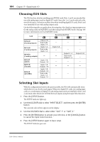
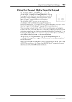
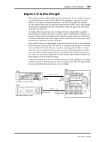
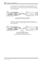
Using the Coaxial Digital Input & Output 187 Using the Coaxial Digital Input & Output The COAXIAL INPUT and OUTPUT phono jacks offer S/PDIF format, 2-channel digital input and output. They can be assigned to individual track pairs, all tracks, or turned off, using the Coaxial I/O function. See "Assigning the Coaxial Input & Output" on page 188 for more information. COAXIAL OUTPUT INPUT The COAXIAL INPUT supports 16-, 20-, and 24-bit STEREO DIGITAL wordlengths. If the wordlength of the signal being input is higher than that selected for recording, the extra bits are discarded, resulting in distor- tion. See "Digital I/O & Wordlength" on page 189 for more information. When recording via the COAXIAL INPUT, the D24 and the source device must be locked to the same wordclock. This can be achieved by configuring the D24 as a wordclock slave, in which case the D24 derives its wordclock from the COAXIAL INPUT, or by locking the D24 and the source device to a common wordclock source. See "Wordclock System Examples" on page 126 for more information. The COAXIAL OUTPUT supports 16-, 20-, and 24-bit wordlengths, and the wordlength of the signal being output will be the same as the recording resolution of the selected project. When a Dual AES/EBU mode wordclock source is selected, the COAXIAL INPUT and OUTPUT do not function. See "Using Dual AES/EBU Mode" on page 186 for more information on Dual AES/EBU mode wordclocks. D24-Owner's Manual
-
 1
1 -
2
-
3
-
4
-
5
-
6
-
7
-
8
-
9
-
10
-
11
-
12
-
13
-
14
-
15
-
16
-
17
-
18
-
19
-
20
-
21
-
22
-
23
-
24
-
25
-
26
-
27
-
28
-
29
-
30
-
31
-
32
-
33
-
34
-
35
-
36
-
37
-
38
-
39
-
40
-
41
-
42
-
43
-
44
-
45
-
46
-
47
-
48
-
49
-
50
-
51
-
52
-
53
-
54
-
55
-
56
-
57
-
58
-
59
-
60
-
61
-
62
-
63
-
64
-
65
-
66
-
67
-
68
-
69
-
70
-
71
-
72
-
73
-
74
-
75
-
76
-
77
-
78
-
79
-
80
-
81
-
82
-
83
-
84
-
85
-
86
-
87
-
88
-
89
-
90
-
91
-
92
-
93
-
94
-
95
-
96
-
97
-
98
-
99
-
100
-
101
-
102
-
103
-
104
-
105
-
106
-
107
-
108
-
109
-
110
-
111
-
112
-
113
-
114
-
115
-
116
-
117
-
118
-
119
-
120
-
121
-
122
-
123
-
124
-
125
-
126
-
127
-
128
-
129
-
130
-
131
-
132
-
133
-
134
-
135
-
136
-
137
-
138
-
139
-
140
-
141
-
142
-
143
-
144
-
145
-
146
-
147
-
148
-
149
-
150
-
151
-
152
-
153
-
154
-
155
-
156
-
157
-
158
-
159
-
160
-
161
-
162
-
163
-
164
-
165
-
166
-
167
-
168
-
169
-
170
-
171
-
172
-
173
-
174
-
175
-
176
-
177
-
178
-
179
-
180
-
 181
181 -
 182
182 -
 183
183 -
 184
184 -
 185
185 -
 186
186 -
 187
187 -
 188
188 -
 189
189 -
 190
190 -
 191
191 -
192
-
193
-
194
-
195
-
196
-
197
-
198
-
199
-
200
-
201
-
202
-
203
-
204
-
205
-
206
-
207
-
208
-
209
-
210
-
211
 |
 |
