Yamaha D24 Owner's Manual - Page 183
Choosing D24 Slots, Selecting Slot Inputs
 |
View all Yamaha D24 manuals
Add to My Manuals
Save this manual to your list of manuals |
Page 183 highlights
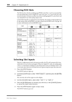
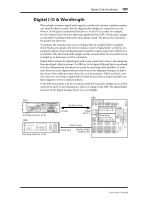
184 Chapter 17-Digital Audio I/O Choosing D24 Slots The D24 has four slots for installing mini YGDAI cards. Slots 1 and 2 are intended for use with analog input cards or digital I/O cards. Since slot 1 or 2 can be selected as the wordclock source, it's best to use these slots when installing digital I/O cards. Slots 3 and 4 are intended for use with analog output cards. Use the following table as a guide when choosing slots. Also listed are input assignments for the analog cards and AES/EBU card when using Dual AES/EBU mode. See page 186 for more information on Dual AES/EBU mode. Card [_1_] Recommended Slot [_2_] [_3_] [_4_] MY8-AD (8 analog inputs) MY4-AD (4 analog inputs) Inputs 1-8 Dual mode: Inputs 1-4 Inputs 1-4 Dual mode: Inputs 1-4 MY4-DA (4 analog outputs) - MY8-AT (ADAT) MY8-TD (Tascam) MY8-AE (AES/EBU) Inputs 1-8 Outputs 1-8 Inputs 1-8 Outputs 1-8 Inputs 1-8 Outputs 1-8 Dual mode: Inputs 1-4 Outputs 1-4 - Inputs 5-8 - - - - - - - - - Outputs 1-4 Dual mode: Outputs 1-4 - Outputs 5-8 - - - - - - Selecting Slot Inputs With the configurations listed in the previous table, the D24 will automatically chose which slot(s) to use for the track inputs. When two digital I/O cards, two analog input cards, or a combination of digital I/O and analog input cards are installed in slots 1 and 2, you must select which slot will feed the track inputs, using the Input Select function. 1 Press the [SETUP] button. The SETUP indicator lights up. 2 Use the JOG/DATA dial to select "INPUT SELECT," and then press the [ENTER] button. The currently selected slot appears on the display. 3 Use the JOG/DATA dial to select either "SLOT 1" or "SLOT 2." 4 Press the [ENTER] button to activate your selection, or the [CANCEL] button to cancel the Input Select function. 5 Press the [SETUP] button again to leave setup. The SETUP indicator goes out. D24-Owner's Manual
-
 1
1 -
2
-
3
-
4
-
5
-
6
-
7
-
8
-
9
-
10
-
11
-
12
-
13
-
14
-
15
-
16
-
17
-
18
-
19
-
20
-
21
-
22
-
23
-
24
-
25
-
26
-
27
-
28
-
29
-
30
-
31
-
32
-
33
-
34
-
35
-
36
-
37
-
38
-
39
-
40
-
41
-
42
-
43
-
44
-
45
-
46
-
47
-
48
-
49
-
50
-
51
-
52
-
53
-
54
-
55
-
56
-
57
-
58
-
59
-
60
-
61
-
62
-
63
-
64
-
65
-
66
-
67
-
68
-
69
-
70
-
71
-
72
-
73
-
74
-
75
-
76
-
77
-
78
-
79
-
80
-
81
-
82
-
83
-
84
-
85
-
86
-
87
-
88
-
89
-
90
-
91
-
92
-
93
-
94
-
95
-
96
-
97
-
98
-
99
-
100
-
101
-
102
-
103
-
104
-
105
-
106
-
107
-
108
-
109
-
110
-
111
-
112
-
113
-
114
-
115
-
116
-
117
-
118
-
119
-
120
-
121
-
122
-
123
-
124
-
125
-
126
-
127
-
128
-
129
-
130
-
131
-
132
-
133
-
134
-
135
-
136
-
137
-
138
-
139
-
140
-
141
-
142
-
143
-
144
-
145
-
146
-
147
-
148
-
149
-
150
-
151
-
152
-
153
-
154
-
155
-
156
-
157
-
158
-
159
-
160
-
161
-
162
-
163
-
164
-
165
-
166
-
167
-
168
-
169
-
170
-
171
-
172
-
173
-
174
-
175
-
176
-
177
-
 178
178 -
 179
179 -
 180
180 -
 181
181 -
 182
182 -
 183
183 -
 184
184 -
 185
185 -
 186
186 -
 187
187 -
 188
188 -
189
-
190
-
191
-
192
-
193
-
194
-
195
-
196
-
197
-
198
-
199
-
200
-
201
-
202
-
203
-
204
-
205
-
206
-
207
-
208
-
209
-
210
-
211
 |
 |
