ZyXEL U-336R User Guide - Page 126
RTS/CTS delay
 |
View all ZyXEL U-336R manuals
Add to My Manuals
Save this manual to your list of manuals |
Page 126 highlights
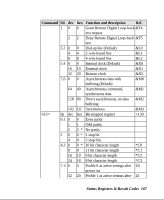
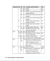
Command bit dec hex Function and description Ref. 24 18 ATX3 X3 32 20 ATX4 X4 40 28 ATX5, error control result code X5 enabled (Default) 48 30 ATX6, error control result code X6 enabled 56 38 ATX7, error control result code X7 enabled 6 0 0 Display result code in numeric V0 format (see S35.7) 64 40 Display result code in verbose V1 format 7 0 0 Modem returns result code Q0 128 80 Modem does not return result Q1 code (see also S40.1) S24= bit dec hex Bit mapped register 2-0 0-7 0-7 Ring Volume control, increment N0-7 of 2 in decimal value 6-4 16- 10- Speaker volume control, L0-7 112 70 increments of 32 in decimal value S25= 0- 0-FF Specify the time delay that DTR +000 255 signal needs to be OFF before it will be recognized, in 10 ms units. If S25=0, the delay time is set to 4 ms S26= dec hex RTS/CTS delay +000 0- 0-FF Set the delay, in 10 millisecond &Rn 255 units between the RTS and modem's CTS response in synchronous mode (see '&Rn' 112 Status Registers & Result Codes
-
 1
1 -
2
-
3
-
4
-
5
-
6
-
7
-
8
-
9
-
10
-
11
-
12
-
13
-
14
-
15
-
16
-
17
-
18
-
19
-
20
-
21
-
22
-
23
-
24
-
25
-
26
-
27
-
28
-
29
-
30
-
31
-
32
-
33
-
34
-
35
-
36
-
37
-
38
-
39
-
40
-
41
-
42
-
43
-
44
-
45
-
46
-
47
-
48
-
49
-
50
-
51
-
52
-
53
-
54
-
55
-
56
-
57
-
58
-
59
-
60
-
61
-
62
-
63
-
64
-
65
-
66
-
67
-
68
-
69
-
70
-
71
-
72
-
73
-
74
-
75
-
76
-
77
-
78
-
79
-
80
-
81
-
82
-
83
-
84
-
85
-
86
-
87
-
88
-
89
-
90
-
91
-
92
-
93
-
94
-
95
-
96
-
97
-
98
-
99
-
100
-
101
-
102
-
103
-
104
-
105
-
106
-
107
-
108
-
109
-
110
-
111
-
112
-
113
-
114
-
115
-
116
-
117
-
118
-
119
-
120
-
 121
121 -
 122
122 -
 123
123 -
 124
124 -
 125
125 -
 126
126 -
 127
127 -
 128
128 -
 129
129 -
 130
130 -
 131
131 -
132
-
133
-
134
-
135
-
136
-
137
-
138
-
139
-
140
-
141
-
142
-
143
-
144
-
145
-
146
-
147
-
148
-
149
-
150
-
151
-
152
-
153
-
154
-
155
-
156
-
157
-
158
-
159
-
160
-
161
 |
 |
